Download
1 / 91
1.81k likes | 3.54k Views
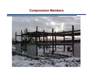
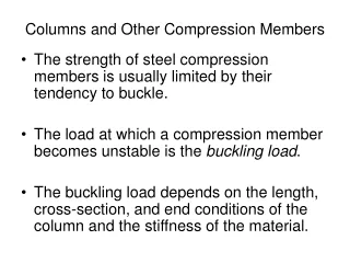
Design of Compression Members. Chapter 03 A. INTRODUCTION When a load tends to squeeze or shorten a member, the stresses produced are said to be compressive in nature and the member is called a compression member . P. Figure 3.1. A Simple Compression Member. P.

E N D
Design of Compression Members Chapter 03 A Dr. Zahid Ahmad Siddiqi
INTRODUCTION When a load tends to squeeze or shorten a member, the stresses produced are said to be compressive in nature and the member is called a compression member. P Figure 3.1. A Simple Compression Member P Dr. Zahid Ahmad Siddiqi
Examples are struts (short compression members without chances of buckling), eccentrically loaded columns, top chords of trusses, bracing members, compression flanges of beams and members that are subjected simultaneously to bending and compressive loads. The term column is usually used for straight vertical member whose length is considerably greater than the cross-sectional dimensions. Dr. Zahid Ahmad Siddiqi
Short vertical members subjected to compressive loads are often called struts or simply compression members. There are two significant differences between the behaviour of tension and compression members, explained as under: • There are no chances of buckling in tension members, whereas the strength of a compression member most dominantly depends on buckling phenomenon. Dr. Zahid Ahmad Siddiqi
The tensile loads tend to hold a member straight even if the member is not initially in one line and is subjected to simultaneous bending moments. In contrast, the compressive loads tend to bend the member out of the plane of the loads due to imperfections, simultaneous bending moment or even without all these. Dr. Zahid Ahmad Siddiqi
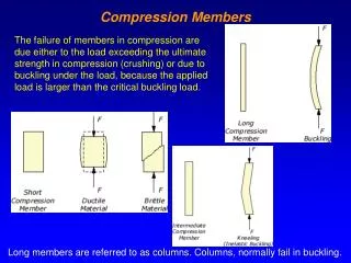
Tests on majority of practical columns show that they will fail at axial stresses well below the elastic limit of the column material because of their tendency to buckle. For these reasons, the strength of compression members is reduced in relation to the danger of buckling depending on length of column, end conditions and cross-sectional dimensions. Dr. Zahid Ahmad Siddiqi
The longer a column becomes for the same cross-section the greater is its tendency to buckle and the smaller is the load it will support. When the length of a compression member increases relative to its cross-section, it may buckle at a lower load. After buckling the load cannot be sustained and the load capacity nearly approaches zero. Dr. Zahid Ahmad Siddiqi
The condition of a column at its critical buckling load is that of an unstable equilibrium as shown in Figure 3.2. Dr. Zahid Ahmad Siddiqi
The three possible states of equilibrium are shown in the same figure. Referring to part (a) of Figure 3.2, if the ball is given movement and released, it comes back to the original position showing a Stable Equilibrium. If ball is displaced and released in part (b), it retains its new position but do not return to its original position. This condition is called Neutral Equilibrium. Dr. Zahid Ahmad Siddiqi
The ball in part (c) is Unstablebecause if the ball is displaced and released it do not return back to its original position and do not retain its new position. In the first case, the restoring forces are greater than the forces tending to upset the system. Due to an infinitesimal small displacement consistent with the boundary conditions or due to small imperfection of a column, a moment is produced in a column trying to bend it. Dr. Zahid Ahmad Siddiqi
At the same time, due to stress in the material, restoring forces are also developed to bring the column back to its original shape. If restoring force is greater than the upsetting moment, the system is stable but if restoring force is lesser than the upsetting moment, the system is unstable. Right at the transition point when restoring force is exactly equal to the upsetting moment, we get neutral equilibrium. Dr. Zahid Ahmad Siddiqi
The force associated with this condition is the critical or buckling load. Returning back to the behaviour of a compression member, relatively rigid end conditions of the member, not allowing the member to rotate freely at these points, reduce the effect of length up to certain extent making the load carrying capacity a little improved. Dr. Zahid Ahmad Siddiqi
Other factors, such as the eccentricity of load application, imperfection of column material, initial crookedness of columns, erection stresses and residual stresses from manufacture, help to buckle the column at a lesser load. Dr. Zahid Ahmad Siddiqi
The presence of rivet or bolt holes in tension members reduces the area available for resisting loads; but in compression members the rivets or bolts are assumed to fill the holes and the entire gross area is available for resisting load. The ideal type of load on a column is a concentric load and the member subjected to this type of load is called concentrically loaded column. Dr. Zahid Ahmad Siddiqi
The load is distributed uniformly over the entire cross-section with the centre of gravity of the loads coinciding with the centre of gravity of the columns. Due to load patterns, the live load on slabs and beams may not be concentrically transferred to interior columns. Dr. Zahid Ahmad Siddiqi
Similarly, the dead and live loads transferred to the exterior columns are, generally, having large eccentricities, as the centre of gravity of the loads will usually fall well on the inner side of the column. In practice, majority of the columns are eccentrically loaded compression members. Dr. Zahid Ahmad Siddiqi
Slight initial crookedness, eccentricity of loads, and application of simultaneous transverse loads produce significant bending moments as the product of high axial loads (P) multiplied with the eccentricity, e. This moment, P x e, facilitates buckling and reduces the load carrying capacity. Eccentricity, e, may be relatively smaller, but the product (P x e) may be significantly larger. This effect is shown in the Figure 3.3. Dr. Zahid Ahmad Siddiqi
The AISC Code of Standard Practice specifies an acceptable upper limit on the out-of-plumbness and initial crookedness equal to the length of the member divided by 500. Stub column is defined as a short compression test specimen that is long enough to allow strain measurements but short enough to avoid elastic and plastic buckling. Dr. Zahid Ahmad Siddiqi
RESIDUAL STRESSES Residual stresses are stresses that remain in a member after it has been formed into a finished product. These are always present in a member even without the application of loads. The magnitudes of these stresses are considerably high and, in some cases, are comparable to the yield stresses (refer to Figure 3.4). Dr. Zahid Ahmad Siddiqi
The causes of presence of residual stresses are as under: • Uneven cooling which occurs after hot rolling of structural shapes produces thermal stresses, which are permanently stored in members. The thicker parts cool at the end, and try to shorten in length. Dr. Zahid Ahmad Siddiqi
While doing so they produce compressive stresses in the other parts of the section and tension in them. Overall magnitude of this tension and compression remain equal for equilibrium. In I-shape sections, after hot rolling, the thick junction of flange to web cools more slowly than the web and flange tips. Dr. Zahid Ahmad Siddiqi
Consequently, compressive residual stress exists at flange tips and at mid-depth of the web (the regions that cool fastest), while tensile residual stress exists in the flange and the web at the regions where they join. Dr. Zahid Ahmad Siddiqi
2. Cold bending of members beyond their elastic limit produce residual stresses and strains within the members. Similarly, during fabrication, if some member having extra length is forced to fit between other members, stresses are produced in the associated members. 3. Punching of holes and cutting operations during fabrication also produce residual stresses. Dr. Zahid Ahmad Siddiqi
Welding also produces the stresses due to uneven cooling after welding. Welded part will cool at the end inviting other parts to contract with it. This produces compressive stresses in parts away from welds and tensile stresses in parts closer to welds. Dr. Zahid Ahmad Siddiqi
SECTIONS USED FOR COLUMNS Single angle, double angle, tee, channel, W-section, pipe, square tubing, and rectangular tubing may be used as columns. Different combinations of these structural shapes may also be employed for compression members to get built-up sections as shown in Figure 3.5. Dr. Zahid Ahmad Siddiqi
Built-up sections are better for columns because the slenderness ratios in various directions can be controlled to get equal values in all the directions. This makes the column economical as far as the material cost is concerned . However the joining and labour cost is generally higher for built-up sections. Dr. Zahid Ahmad Siddiqi
The total cost of these sections may become less for greater lengths. The joining of various elements of a built-up section is usually performed by using lacing. LIMITING SLENDERNESS RATIO The slenderness ratio of compression members should preferably not exceed 200. Dr. Zahid Ahmad Siddiqi
INSTABILITY OF COLUMNS When buckling occurs in columns, we say that columns have become unstable. The instability may be due to local or overall buckling. Dr. Zahid Ahmad Siddiqi
Local Instability During local instability, the individual parts or plate elements of cross-section buckle without overall buckling of the column. Width/thickness ratio of each part gives the slenderness ratio (λ=b/t), which controls the local buckling. Dr. Zahid Ahmad Siddiqi
Local buckling should never be allowed to occur before the overall buckling of the member except in few cases like web of a plate girder. An Un-stiffened Element is a projecting piece with one free edge parallel to the direction of the compressive force. The example is half flange AB in figure 3.6. Dr. Zahid Ahmad Siddiqi
A Stiffened Element is supported along the two edges parallel to the direction of the force. The example is web AC in the same figure. For un-stiffened flange of figure, b is equal to half width of flange (bf/2) and t is equal to tf. Hence, bf/2tf ratio is used to find λ. Dr. Zahid Ahmad Siddiqi
For stiffened web, h is the width of web and tw is the thickness of web and the corresponding value of λ or b/t ratio is h/tw, which controls web local buckling. Dr. Zahid Ahmad Siddiqi
Overall Instability In case of overall instability, the column buckles as a whole between the supports or the braces about an axis whose corresponding slenderness ratio is bigger as shown in Figures 3.7 to 3.9. Dr. Zahid Ahmad Siddiqi
Note: Single angle sections may buckle about their weak axis (z-axis shown in Design Aids and Figure 3.10). Calculate Le / rzto check the slenderness ratio. In general, all un-symmetric sections having non-zero product moment of inertia (Ixy) have a weak axis different from the y-axis. Dr. Zahid Ahmad Siddiqi
Unsupported Length It is the length of column between two consecutive supports or braces denoted by Lux or Luy in the x & y directions, respectively. A different value of unsupported length may exist in different directions and must be used to calculate the corresponding slenderness ratios. Dr. Zahid Ahmad Siddiqi
To calculate unsupported length of a column in a particular direction, only the corresponding supports and braces are to be considered neglecting the bracing preventing buckling in the other direction. Dr. Zahid Ahmad Siddiqi
Effective Length Of Column The length of the column corresponding to one-half sine wave of the buckled shape or the length between two consecutive inflection points or supports after buckling is called the effective length. Dr. Zahid Ahmad Siddiqi
BUCKLING OF STEEL COLUMNS Buckling is the sudden lateral bending produced by axial loads due to initial imperfection, out-of-straightness, initial curvature, or bending produced by simultaneous bending moments. Chances of buckling are directly related with the slenderness ratio KL/rand hence there are three parameters affecting buckling. • Effective length factor (K), which depends on the end conditions of the column. Dr. Zahid Ahmad Siddiqi