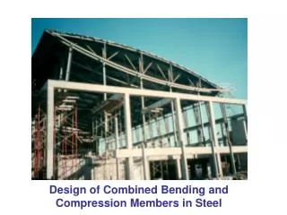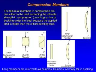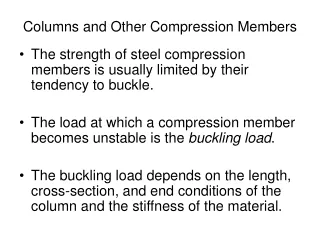
Compression Members
Compression Members. COLUMN STABILITY. A. Flexural Buckling Elastic Buckling Inelastic Buckling Yielding B. Local Buckling – Section E7 pp 16.1-39 and B4 pp 16.1-14 C. Lateral Torsional Buckling. AISC Requirements. CHAPTER E pp 16.1-32. Nominal Compressive Strength. AISC Eqtn E3-1.
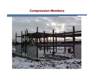

Compression Members
E N D
Presentation Transcript
COLUMN STABILITY • A.Flexural Buckling • Elastic Buckling • Inelastic Buckling • Yielding • B. Local Buckling – Section E7 pp 16.1-39 • and B4 pp 16.1-14 • C. Lateral Torsional Buckling
AISC Requirements CHAPTER E pp 16.1-32 Nominal Compressive Strength AISC Eqtn E3-1
AISC Requirements LRFD
In Summary - Definition of Fe Elastic Buckling Stress corresponding to the controlling mode of failure (flexural, torsional or flexural torsional) Fe: Theory of Elastic Stability (Timoshenko & Gere 1961) Flexural Buckling Torsional Buckling 2-axis of symmetry Flexural Torsional Buckling 1 axis of symmetry Flexural Torsional Buckling No axis of symmetry AISC Eqtn E4-4 AISC Eqtn E4-5 AISC Eqtn E4-6
Column Design Tables Assumption : Strength Governed by Flexural Buckling Check Local Buckling Column Design Tables Design strength of selected shapes for effective length KL Table 4-1 to 4-2, (pp 4-10 to 4-316) Critical Stress for Slenderness KL/r table 4.22 pp (4-318 to 4-322)
Design of Members in Compression • Selection of an economical shape: Find lightest shape • Usually category is defined beforehand, e.g. W, WT etc • Usually overall nominal dimensions defined in advance because of architectural and other requirements. USE OF COLUMN LOAD TABLES IF NOT APPLICABLE - TRIAL AND ERROR
EXAMPLE I – COLUMN LOAD TABLES A compression member is subjected to service loads pf 165 dead and 535 kips live. The member is 26 feet long and pinned at each end LRFD Calculate factored load Required Design Strength Enter Column Tables with KL=(1)(26)=26 ft OK
EXAMPLE I – COLUMN LOAD TABLES A compression member is subjected to service loads pf 165 dead and 535 kips live. The member is 26 feet long and pinned at each end ASD Calculate factored load Required Allowable Strength Enter Column Tables with KL=(1)(26)=26 ft OK
EXAMPLE Ii – COLUMN LOAD TABLES Select the lightest W-shape that can resist a service dead load of 62.5 kips and a service live load of 125 kips. The effective length is 24 feet. Use ASTM A992 steel LRFD Calculate factored load and required strength Enter Column Tables with KL=(1)(24)=24 ft No Footnote: No need to check for local buckling
IF COLUMNS NOT APPLICABLE • Assume a value for Fcr • Determine required area LRFD ASD
IF COLUMNS NOT APPLICABLE 3 Select a shape that satisfies area requirement 4 Compute Fcr for the trial shape • Revise if necessary • If available strength too close to required value try next tabulated value • Else repeat 1-4 using Fcr of trial shape 6 Check local stability and revise if necessary
Example Select a W18 shape of A992 steel that can resist a service dead load of 100 kips amd a service live load of 300 kips. Effective length KL=26 ft Calculate factored load and required strength Try Required Area
Example Select a W18 shape of A992 steel that can resist a service dead load of 100 kips amd a service live load of 300 kips. Effective length KL=26 ft Try W 18x71 OK Available Area OK Slenderness Euler’s Stress Elastic Buckling Slenderness Limit ELASTIC BUCKLING
Example Select a W18 shape of A992 steel that can resist a service dead load of 100 kips amd a service live load of 300 kips. Effective length KL=26 ft Critical Stress Design Strength NG
Example Select a W18 shape of A992 steel that can resist a service dead load of 100 kips amd a service live load of 300 kips. Effective length KL=26 ft Assume NEW Critical Stress Required Area
Example Select a W18 shape of A992 steel that can resist a service dead load of 100 kips amd a service live load of 300 kips. Effective length KL=26 ft Try W 18x119 OK Available Area OK Slenderness Euler’s Stress Elastic Buckling Slenderness Limit ELASTIC BUCKLING
Example Select a W18 shape of A992 steel that can resist a service dead load of 100 kips amd a service live load of 300 kips. Effective length KL=26 ft Critical Stress Design Strength NG This is very close, try next larger size
Example Select a W18 shape of A992 steel that can resist a service dead load of 100 kips amd a service live load of 300 kips. Effective length KL=26 ft Try W 18x130 Available Area OK Slenderness Euler’s Stress Elastic Buckling Slenderness Limit ELASTIC BUCKLING
Example Select a W18 shape of A992 steel that can resist a service dead load of 100 kips amd a service live load of 300 kips. Effective length KL=26 ft Critical Stress Design Strength OK
Effective Length Factor-Alingnment Charts Use alignment charts (Structural Stability Research Council SSRC) AISC Commentary Figure C-C2.3 nad C-C2.4 p 16-.1-241 • Connections to foundations • (a) Hinge • G is infinite - Use G=10 • (b) Fixed • G=0 - Use G=1.0 Assumption of Elastic Behavior is violated when Inelastic Flexural Buckling
Example Joint A Joint B Joint C Sway Uninhibited Pinned End
Example AISC Commentary Figure C-C2.3 nad C-C2.4 p 16-.1-241 COLUMN AB COLUMN BC
More on Effective Length Violated
Alingnment Charts & Inelastic Behavior Elastic Inelastic Stiffness Reduction Factor SRF: Table 4-21 AISC Manual pp 4-317
Example Compute Stiffness Reduction Factor per LRFD for an axial compressive stress of 25 ksi and Fy=50 ksi