Download
1 / 25
250 likes | 338 Views
Explore the vital data analysis techniques and mission requirements of the Generation-X Telescope for precise adjustment and measurement on orbit. Discover key objectives and technical concepts for successful operations.

E N D
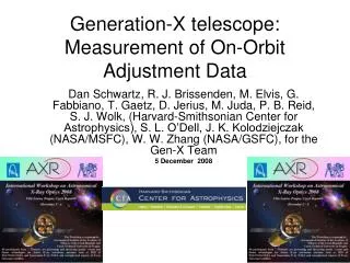
Generation-X telescope: Measurement of On-Orbit Adjustment Data Dan Schwartz, R. J. Brissenden, M. Elvis, G. Fabbiano, T. Gaetz, D. Jerius, M. Juda, P. B. Reid, S. J. Wolk, (Harvard-Smithsonian Center for Astrophysics), S. L. O’Dell, J. K. Kolodziejczak (NASA/MSFC), W. W. Zhang (NASA/GSFC), for the Gen-X Team 5 December 2008
Generation-X Science Objectives • Detection of first black holes at z~10-20 • Evolution of Black Holes, Galaxies, Elements, from formation to the present • Behavior of matter in extreme environments of Density, Gravity, Magnetic fields, Kinetic Energy.
Key Mission Requirements: • Large Area, ~50 m2 at 1 keV • Fine angular resolution, 0."1
A Gen-X Mirror Configuration • 204 shells, 0.2 – 0.4 mm thick glass • 16m outer diameter, (partially filled) • 8.3m completely filled, 3.5m inner diameter • 60m focal length • 1m Shell length (each, P or S) • 5' radius FOV • 10mm shell clearance
Actuator Configuration Concept: continuous Piezo deposition, electrically divided • Correct < 0.025 /mm =40mm period • Oversample: 20mm actuators axially, 50 per plate • Circumference tolerance ~10x worse, 200 mm actuators, 5 axial strips per plate. • Oversample measurements: 100 per axial strip.
Raytrace Study Objectives: • Detector requirements • Placement • Resolution • Can we detect deviations from ideal figure? • Are the measurements practical?
Raytrace Study • Shells 1, 2, 203, 204 • Uniform incident rays, perfect reflection • Perfect Wolter I Geometry • Perfect kinematic mounting, alignment • Trace single axial strip • Perturb surface figure by low order Legendre Polynomials • Introduce "toy" actuators
Measure ~50,000 axial positions (1cm2), ~1000 at once. 500s exposure to Sco X-1 at 2 104 s-1 gives 104 counts per azimuth per ring. Iterate 10 times at 50% duty cycle, factor 10 margin, 120day initial adjustment Resolve 100 bins with detector resolution 10µ. Require 8.17m forward of focus.
Spacing of the figure detector to resolve 40 shells into 100 bins
Ring profile for∑Pn distortions proportional to 0.0001/n mm.Image size in focal plane is 0."21 rms and 0."11 half-power Ring Profile can Detect Figure Errors!
Poorer quality figure spreads the ring further 10" rms 19" rms 2.2" rms 4.8" rms
Requirements on Figuring Detector • X-ray range ~0.2 – 4 keV • Count 2x10⁴ s-1 per field • Resolve events to 10µm • 2-4 units, 100mm x 100mm field each • Position ~1 to 10 m forward of focus • accuracy ~1cm axial, 1mm radial • Radial positioning knowledge better than 10 µ
Issues to Investigate: • What is the required initial quality? • Use optical Hartmann test? • Algorithm Concepts: • Measure Derivatives • Simulated annealing • “forward-fit" a distorted raytrace model shell to the ring profile measurement • Handling the P/H Degeneracy? • Use =983.17mm? • Fix Hyperboloid and adjust Paraboloid?
Conclusions (so far) • Ring Profile, Position and Spread are extremely sensitive to figure quality • On-orbit Measurements are feasible • Actuator design is critical for • Sufficient correction amplitude • Avoiding transfer of low spatial frequency figure errors to higher frequencies