Download
1 / 29
290 likes | 442 Views
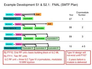
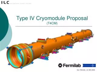
Type IV Cryomodule Proposal (T4CM). Don Mitchell, 16 JAN 2006. Design Reference: TTF III+. TTF III+ Cryomodule. Courtesy of DESY. ILC Cryo Design Considerations. Move quad package to middle of cryomodule to achieve better support and alignment.

E N D
Type IV Cryomodule Proposal(T4CM) Don Mitchell, 16 JAN 2006
Design Reference: TTF III+ D. Mitchell, FNAL
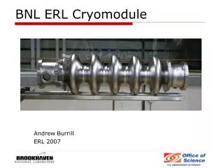
TTF III+ Cryomodule Courtesy of DESY D. Mitchell, FNAL
ILC Cryo Design Considerations • Move quad package to middle of cryomodule to achieve better support and alignment. • Shorten cavity-to-cavity interconnect and simplify for ease of fabrication and cost reduction. Possible superconducting joint. • Overall improved packing factor. • Minimize direct heat load to cavity through MC. • Simplify the assembly procedure. • MLI redesign to reduce hands-on labor costs. • More robust design to survive shipping. • Reliability of tuner motors in cold operation. • Etc. (we’ve heard many suggestions) D. Mitchell, FNAL
Increase diameter beyond X-FEL Increase diameter beyond X-FEL Review 2-phase pipe size and effect of slope D. Mitchell, FNAL
T4CM Proposal (not the final ILC design) Minor changes to address major concerns. • Magnet alignment and vibration issues. • Cryomodule with and without magnet package • Define BPM, Steering, and Quad parameters • Possible option for separate magnet cryovessel • Reduced cavity length (which tuner design?) • Reduced cavity spacing (new interconnect) • Need for functional Fast-Tuner Current Cryo3 D. Mitchell, FNAL
Conceptual Model Development D. Mitchell, FNAL
Assumes use ofXFEL Main Coupler Graphics from Terry Garvey D. Mitchell, FNAL
Generation 4, T4CM D. Mitchell, FNAL
Design Changes Beware of a ripple effect! D. Mitchell, FNAL
Design Change Example: Modified Cavity Length • Known Impacts • Vessel weldment • Linac Layout • Main coupler position • Magnetic shield design • Integrated with supplier • HGR pipe weldement • cryogenic piping details • Invar rod length • including thermal shrinkage calculations • Wire position monitor locations • Waveguide connections • Helium supply pipe lengths D. Mitchell, FNAL
Design Change Example: Modified Cavity Length • Potential Impacts • Transportation fixtures • Etching jackets • EP process tooling • High pressure rinse • Process tooling • Controls programming D. Mitchell, FNAL
T4CM Proposed Cavity w/ Bladetuner D. Mitchell, FNAL
Cavity Spacing 71.8 mm D. Mitchell, FNAL
Cavity Dimensions D. Mitchell, FNAL
Cryomodule – A working 3-D model D. Mitchell, FNAL
Excel driven 3-DI-DEAS Model D. Mitchell, FNAL
Multi-linked Excel Sheets drive 3-D CAD D. Mitchell, FNAL
Excel usage integrates engineering calculations into the 3-D CAD process! D. Mitchell, FNAL
Automatically adjusts for thermal contraction and component lengths D. Mitchell, FNAL
10457 mm 11387 mm 11750 mm D. Mitchell, FNAL
Note:Does not include other components installed within the accelerator nor a possible increased magnet package length. Packing factor Active length = 1036.2 mm x 24 cavities = 24868.6 mm Packing Factor = 24868.6 / 35109 = 0.71 35109mm 1036.2 mm D. Mitchell, FNAL
No matter how simple the proposed changes are, this is no small task! • Concept development / Collaboration • Engineering analyses to appropriate standards • Part design • 3-D modeling (concepts to reality) • ~750 parts / assembly drawings • Vendor integration • Procurement process • Fabrication • Assembly • Installation D. Mitchell, FNAL
Design coordination sample worksheet D. Mitchell, FNAL
Free 3-D Visualization with UGS JT2GO D. Mitchell, FNAL
Proposed 4th Generation Design • 2 Vessels, ΔLength=1293.8 mm (w & w/o Magnet package) • Cavity string supported and aligned by 3 support posts. • Magnet independently aligned but still supported from the 300mm HGR pipe. (HGR Pipe may need to be resized) • Support post locations may be identical in both vessels to simplify the tooling. • HOM absorber in interconnect region. What length? • Smaller cav-to-cav connection (71.8mm) • BPM, Quad magnet, and steering magnets are combined into one magnet package. Total length currently assumed to be 1222 mm. Should this length be increased to 1500mm? • TTF III cavity utilizes short end-tube for both ends. Length reduced to 105.6 mm. • Possible use of Bladetuner due to the shortened cavity length. • New Magnetic Shield design is required. • All ports and flanges will be metric and ISO style. D. Mitchell, FNAL
T4CM will differ from Type III+ • Cavity iris-to-iris spacing reduced to 283 mm • String length changes from 12200mm to ~12565mm. • Slow tuner modified to allow closer cavity-to-cavity spacing (could mean switching to bladetuner design, but choice still open). • Fast tuner -- new design needed. • Quad/corrector/BPM package under center post, hung from 300 mm tube, not on rollers (diverging from X-FEL). • Two major module types, one with quad and one without. D. Mitchell, FNAL
More differences of T4CMfrom Type III+ • Interconnect features modified to accommodate an input coupler at end of cryostat as well as a new HOM absorber. • Quad current leads may be new, with local impact on thermal shields and vacuum vessel ports. May need large access ports as well. • Provisions for quad power lead connection at center of module. • Address magnet alignment issues. • Some pipe sizes will be increased for lower pressure drops with high flow rates -- would like to retain long cryogenic unit lengths up to limit of 300 mm pipe and cryo plants. Present effort includes re-analysis of heat loads, flow rates, and cryogenic system thermal process. D. Mitchell, FNAL
Some critical open design issues • Quad/corrector/BPM package is a major unknown right now and goes into the heart of the module. • Tuner details, slow and fast, but especially fast tuner • Cavity-to-cavity interconnect design. • Vibrational analysis, which will be compared to measurements for verification of the model for future design work. • Magnetic shield re-design. • Development of module and module component tests. • Verification of cavity positional stability with thermal cycles. • Design of test instrumentation for the module. • Robustness for shipping, analysis of shipping restraints and loads, shipping specifications. • Active quad movers(?) A complication D. Mitchell, FNAL