Download
1 / 21
210 likes | 341 Views
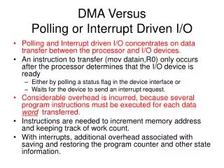
Computer Organization & Design Microcode for Control Sec. 5.7 (CDROM) Appendix C (CDROM) / 3055-05 / pdf / lec_3a_notes.pdf. The Processor: Datapath & Control. We're ready to look at an implementation of the MIPS Simplified to contain only: memory-reference instructions: lw, sw

E N D
Computer Organization & Design Microcode for Control Sec. 5.7 (CDROM)Appendix C (CDROM)/ 3055-05 / pdf / lec_3a_notes.pdf
The Processor: Datapath & Control • We're ready to look at an implementation of the MIPS • Simplified to contain only: • memory-reference instructions: lw, sw • arithmetic-logical instructions: add, sub, and, or, slt • control flow instructions: beq, j • Generic Implementation: • use the program counter (PC) to supply instruction address • get the instruction from memory • read registers • use the instruction to decide exactly what to do • All instructions use the ALU after reading the registers Why? memory-reference? arithmetic? control flow?
Control • e.g., what should the ALU do with this instruction • Example: lw $1, 100($2) 35 2 1 100 op rs rt 16 bit offset • ALU control input000 AND 001 OR 010 add 110 subtract 111 set-on-less-than • Why is the code for subtract 110 and not 011?
ALUOp computed from instruction type Control • Must describe hardware to compute 3-bit ALU control input • given instruction type 00 = lw, sw 01 = beq, 11 = arithmetic • function code for arithmetic • Describe it using a truth table (can turn into gates):
Implementing the Control • Value of control signals is dependent upon: • what instruction is being executed • which step is being performed • Use the information we’ve accumulated to specify a finite state machine • specify the finite state machine graphically, or • use microprogramming • Implementation can be derived from specification
Graphical Specification of FSM • How many state bits will we need? 10 states, < 2^4 4 bits
Finite State Machine for Control • Implementation: Datapath Control Logic Instruction Register Opcode Field
PLA Implementation • If I picked a horizontal or vertical line could you explain it? Op5 Op4 Op3 Op2 Op1 Op0 State3 State2 State1 State0 PCWrite PCWriteCond IorD MemRead MemWrite IRWrite MemtoReg PCSource1 PCSource0 ALUop1 ALUop0 ALUsrce1 ALUsrce0 ALUsrce RegWrite RegDst NextState3 NextState2 NextState1 NextState0
PLA Implementation Orange dots are AND gates • Red color shows lines that are "high" or "1" Op5 = 1 Op4 = 0 Op3 = 0 Op2 = 0 Op1 = 1 Op0 = 0 State3 = 0 State2 = 0 State1 = 0 State0 = 1 Grey dots are OR gates, 1 or hi-Z "1" Output PCWrite = 0 PCWriteCond = 0 IorD = 0 MemRead = 0 MemWrite = 0 IRWrite = 0 MemtoReg = 0 PCSource1 = 0 PCSource0 = 0 ALUop1 = 0 ALUop0 = 0 ALUsrce1 =1 ALUsrce0 = 1 ALUsrce = 0 RegWrite = 0 RegDst = 0 NextState3 = 0 NextState2 = 0 NextState1 = 1 NextState0 = 0 State 1 (0001) is followed by state 2 (0010) if Op = 100010, with ALUsrce0 and ALUsrce1 set to "1" (true).
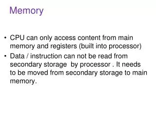
m n ROM Implementation • ROM = "Read Only Memory" • values of memory locations are fixed ahead of time • A ROM can be used to implement a truth table • if the address is m-bits, we can address 2m entries in the ROM. • our outputs are the bits of data that the address points to.m is the "height", and n is the "width" 0 0 0 0 0 1 1 0 0 1 1 1 0 0 0 1 0 1 1 0 0 0 1 1 1 0 0 0 1 0 0 0 0 0 0 1 0 1 0 0 0 1 1 1 0 0 1 1 0 1 1 1 0 1 1 1
ROM Implementation • How many inputs are there? 6 bits for opcode, 4 bits for state = 10 address lines (i.e., 210 = 1024 different addresses) • How many outputs are there? 16 datapath-control outputs, 4 state bits = 20 outputs • ROM is 210 x 20 = 20K bits (and a rather unusual size) • Rather wasteful, since for lots of the entries, the outputs are the same — i.e., opcode is often ignored
ROM vs PLA • Break up the table into two parts — 4 state bits tell you the 16 outputs, 24 x 16 bits of ROM — 10 bits tell you the 4 next state bits, 210 x 4 bits of ROM — Total: 4.3K bits of ROM • PLA is much smaller — can share product terms — only need entries that produce an active output — can take into account don't cares • Size is (#inputs #product-terms) + (#outputs #product-terms) For this example = (10x17)+(20x17) = 460 PLA cells • PLA cells usually about the size of a ROM cell (slightly bigger)
Another Implementation Style • Complex instructions: the "next state" is often current state + 1 Control Unit PLA or ROM Datapath State Address Select Logic Instruction Register Opcode Field
Details State Add 1 AddrCtl Dispatch ROM 2 Dispatch ROM 1 Address Select Logic Instruction Register Opcode Field
Microprogramming • What are the “microinstructions” ? Control Unit Microcode Memory Datapath Microprogram Counter Address Select Logic Instruction Register Opcode Field
Microprogramming • A specification methodology • appropriate if hundreds of opcodes, modes, cycles, etc. • signals specified symbolically using microinstructions • Will two implementations of the same architecture have the same microcode? • What would a microassembler do?
Maximally vs. Minimally Encoded • No encoding: • 1 bit for each datapath operation • faster, requires more memory (logic) • used for Vax 780 — an astonishing 400K of memory! • Lots of encoding: • send the microinstructions through logic to get control signals • uses less memory, slower • Historical context of CISC: • Too much logic to put on a single chip with everything else • Use a ROM (or even RAM) to hold the microcode • It’s easy to add new instructions
Microcode: Trade-offs • Distinction between specification and implementation is sometimes blurred • Specification Advantages: • Easy to design and write • Design architecture and microcode in parallel • Implementation (off-chip ROM) Advantages • Easy to change since values are in memory • Can emulate other architectures • Can make use of internal registers • Implementation Disadvantages, SLOWER now that: • Control is implemented on same chip as processor • ROM is no longer faster than RAM • No need to go back and make changes
The Big Picture Finite State Diagram Initial Representation Microprogram Microprogram Counter + Dispatch ROMS Sequencing Control Explicit Next-State Function Truth Tables Logic Equation Logic Representation Programmable Logic Array Read Only Memory Implementation Technique