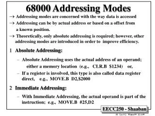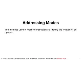
Addressing Modes
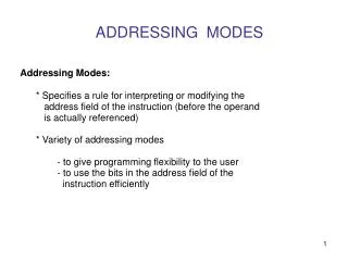
Data Addressing Modes. Fig.3.1 illustrates the MOV instruction and defines the direction of data flowFig.3.2 shows all possible data variations of the data-addressing modes using the MOV instructionRegister adressing:MOV CX,DX or MOV ECX,EDXImmediate addressing: MOV AL,22H or MOV

Addressing Modes
E N D
Presentation Transcript
1. Addressing Modes A Course in Microprosessor
Electrical Engineering Department
University of Indonesia
2. Data Addressing Modes Fig.3.1 illustrates the MOV instruction and defines the direction of data flow
Fig.3.2 shows all possible data variations of the data-addressing modes using the MOV instruction
Register adressing: MOV CX,DX or MOV ECX,EDX
Immediate addressing: MOV AL,22H or MOV EAX,12345678H
Direct addressing: MOV CX,LIST
3. Data Addressing Modes (cont�d) Base-plus-index adressing: MOV [BX+DI], CL or MOV [EAX+EBX],CL
Register relative addressing: MOV AX,[BX+4] or MOV AX,ARRAY[BX]
Base relative-plus-index addressing: MOV AX,ARRAY[BX+DI] or MOV AX,[BX+DI+4]
Scaled-index addressing: MOV EDX,[EAX+4*EBX]
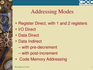
4. Register Addressing It is the most common form and is the easiest to apply
Microprocessor contains 8-bit, 16-bit, 32-bit registers
Never mix an 8-bit register with a 16-bit register, 16-bit register with a 32-bit register, etc., because this results in an error when assembled
Table 3.1 shows many variations of register move instructions
Fig.3.3 shows the operation of the MOV BC,CX instruction
5. Register Addressing Example 3.1 shows a sequence of assembled instructions that copy various data between 8-, 16-, and 32-bit registers
6. Immediate Addressing The term immediate implies that the data immediately follow the hexadecimal opcode in the memory
Immediate are constant data
The MOV immediate instruction transfers a copy of the immediate data into a register or a memory location
Fig.3.4 shows the source data (sometimes preceded by #) overwrite the destination data
The instruction copies the 13456H into register AX
7. Register Addressing Example 3.2 shows various immeidate instructions in a short program that placess a 0000H into the 16-bit registers AX, BX, CX
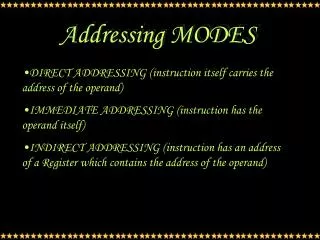
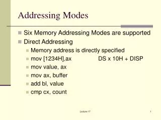
8. Direct Data Addressing There two basic forms of direct data addressing:
direct addressing, which applies to a MOV bet-ween a memory location and AL, AX or EAX
displacement addressing, which applies to almost any instruction in the instruction set
Direct Addressing: MOV AL,DATA (Fig.3.5)
Table 3.3 lists the three direct addressed instruc-tion
A MOV instruction is 3-byte long instruction
9. Direct Data Addressing Displacement Addressing: MOV CL,DATA
almost identical with direct addressing except that the instruction is four bytes wide
10. Register Indirect Addressing It allows data to be addressed at any memory location through an offset address held in any of the following register: BP, BX, DI, and SI
MOV AX,[BX] Fig.3.6
Data segment is used by default with register indirect addressing or any other addressing mode that uses BX, DI, or SI to address memory
If register BP addresses memory, the stack segment is used by default
11. Register Indirect Addressing Sometimes, indirect addressing requires spe-cifying the size of the data with the special assembler directive BYTE PTR, WORD PTR or DWORD PTR
These indicate the size of the memory data addressed by the memory pointer (PTR)
Indirect addressing allows a program to refer to a tabular data located in the memory sys-tem (Fig.3.7 & Example 3.6)
12. Base-Plus-Index Addressing It indirectly addresses memory data
In 8086 - 80286, this use a base register (BP or BX, holds the beginning location of a memory array) and an index register (DI or SI, ) to indirectly addresses memory
In 80386 and above, this type of addressing allows the combination of any two 32-bit extended registers except #SP
MOV DL, [EAX+EBX]
Figure 3.8 shows the sample instruction of locating data with this scheme
13. Base-Plus-Index Addressing (cont�d) The major use of this type of addressing is to address elements in a memory array
Fig.3.9 shows the use of BX (base) and DI (index) to access an element in an array of data)
Study Table 3.6 and Example 3.7 as well
14. Register Relative Addressing In its, the data in a segment of memory are addressed by adding the displacement to the contents of a base ro and index register (BP, BX, DI, or SI)
Fig.3.10 shows the operation of the MOV AX,[BX+ 1000H] instruction
The displacement can be a number added to the register within the [ ], as in MOV AL,[DI+2], or it can be a displacement substracted from the register, as in MOV AL,[SI-1]
15. Register Relative Addressing (cont�d) It is possible to address array data with regis-ter relative addressing such as one does with base-plus-index addressing
See Fig.3.11 and study the example 3.8
16. Base Relative-Plus-Index Addressing This mode often addresses a two-dimension-al array of memory data
It is the least-used addressing mode (i.e., too complex for frequent use in a program)
Fig.3.12 shows how the instruction MOV AX, [BX+SI+100H]
Addressing arrays with base relative-plus-index addressing
the displacement addresses the file
the base register addresses a record
the index register addresses an element of a record
Study Example 3.9 and Fig.3.13
17. Scaled-Index Addressing This type of addressing is unique to the 80386 - Pentium Pro
It uses two 32-bit registers (a base register and an index register) to access the memory
The second register (index) is multiplied by a scaling factor (either 1X, 2X, 4X, or 8X)
MOV AX,[EDI+2*ECX]
See Example 3.10 and Table 3.9
18. Data Structures A data structure is used to specify how information is stored in a memory array; it can be quite useful with application that use arrays
The start of a structure is identified with the STRUC directive and ended with the ENDS
See Example 3.11
When data are addressed in a structure, use the structure name and the field name to se-lect a field from the structure (Example 3.12)
19. Program Memory Addressing Program memory-addressing modes (JMP and CALL) consist of three distinct forms: direct, relative, and indirect
Direct Program Memory Addressing
The instruction store the address with the op-code
20. Program Memory-Addressing Modes Program memory-addressing modes (JMP and CALL) consist of three distinct forms: direct, relative, and indirect
Direct Program Memory Addressing
The instructions store the address with the op-code
See Fig.3.14
It is called a far jump because it can jump to any memory location for the next instruction
21. Program Memory Addressing Modes (contd) Relative Program Memory Addressing
The term relative means �relative to the IP�
See Fig.3.15
JMP instruction is a one-byte instruction with a one-byte or two-byte displacement that adds to the instruction pointer
Relative JMP and CALL instructions contain either an 8-bit or a 16-bit signed displacement that allows a forward memory reference or a reverse memory reference
22. Program Memory Addressing Modes (contd) Indirect Program Memory Addressing
Table 3.10 lists some acceptable indirect program jump instructions, which can use any 16-bit register, any relative register, and any re-lative register with a displacement
If a 16-bit register holds the address of a JMP instruction, the jump is near
If a relative register holds the address, the jump is also considered an indirect jump
Fig.3.16 shows a jump table that is stored begin-ning at memory location TABLE
23. Stack Memory-Addressing Modes Stack holds data temporarily and stores return addresses for procedures
The stack memory is LIFO memory
Use PUSH instruction to place data onto stack
Use POP instruction to remove data from stack
The stack memory is maintained by two registers: SP or ESP, and SS
Study Fig.3.17
The PUSHA and POPA either push or pop all of the register, except the segment register, on the stack (see example 3.14)