Addressing Modes ( Week4)
Addressing Modes ( Week4). Generating Memory Addresses.


Addressing Modes ( Week4)
E N D
Presentation Transcript
Addressing Modes(Week4) CENG 222 - Spring 2012-2013 Dr. Yuriy ALYEKSYEYENKOV
Generating Memory Addresses Let us return to example. The purpose of the instruction block starting at LOOP is toadd successive numbers from the list during each pass through the loop. Hence, the Loadinstruction in that block must refer to a different address during each pass. How are theaddresses specified? The memory operand address cannot be given directly in a single Loadinstruction in the loop. Otherwise, it would need to be modified on each pass through theloop. As one possibility, suppose that a processor register, Ri, is used to hold the memoryaddress of an operand. If it is initially loaded with the address NUM1 before the loop isentered and is then incremented by 4 on each pass through the loop, it can provide theneeded capability. CENG 222 - Spring 2012-2013 Dr. Yuriy ALYEKSYEYENKOV
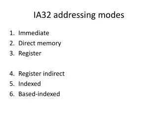
Addressing Modes We have now seen some simple examples of assembly-language programs. In general,a program operates on data that reside in the computer’s memory. These data canbeorganized in a variety of ways that reflect the nature of the information and how it is used.Programmers use data structures such as lists and arrays for organizing the data used incomputations.Programs are normally written in a high-level language, which enables the programmerto conveniently describe the operations to be performed on various data structures. Whentranslating a high-level language program into assembly language, the compiler generatesappropriate sequences of low-level instructions that implement the desired operations. The different ways for specifying the locations of instruction operands are known as addressingmodes. In this section we present the basic addressing modes found in RISC-style processors.A summary is provided in Table. CENG 222 - Spring 2012-2013 Dr. Yuriy ALYEKSYEYENKOV
Addressing Modes CENG 222 - Spring 2012-2013 Dr. Yuriy ALYEKSYEYENKOV
Implementation of Variables and Constants Variables are found in almost every computer program. In assembly language, a variable is represented by allocating a register or a memory location to hold its value. This value can be changed as needed using appropriate instructions. The program analyzed uses only two addressing modes to access variables. We access an operand by specifying the name of the register or the address of the memory location where the operand is located. The precise definitions of these two modes are: Register mode—The operand is the contents of a processor register; the name of the register is given in the instruction. Absolute mode—The operand is in a memory location; the address of this location is given explicitly in the instruction. CENG 222 - Spring 2012-2013 Dr. Yuriy ALYEKSYEYENKOV
Implementation of Variables and Constants The instruction Add R4, R2, R3 uses the Register mode for all three operands. Registers R2 and R3 hold the two source operands, while R4 is the destination. The Absolute mode can represent global variables in a program. A declaration such as Integer NUM1, NUM2, SUM; in a high-level language program will cause the compiler to allocate a memory location to each of the variables NUM1, NUM2, and SUM. Whenever they are referenced later in the program, the compiler can generate assembly-language instructions that use the Absolute mode to access these variables. The Absolute mode is used in the instruction Load R2, NUM1 which loads the value in the memory location NUM1 into register R2. CENG 222 - Spring 2012-2013 Dr. Yuriy ALYEKSYEYENKOV
Implementation of Variables and Constants Constants representing data or addresses are also found in almost every computer program. Such constants can be represented in assembly language using the Immediate addressing mode. Immediate mode—The operand is given explicitly in the instruction. For example, the instruction Add R4, R6, #200 adds the value 200 to the contents of register R6, and places the result into register R4. A common convention is to use the number sign (#) in front of the value to indicate that this value is to be used as an immediate operand. In the addressing modes that follow, the instruction does not give the operand or its address explicitly. Instead, it provides information from which an effective address (EA) can be derived by the processor when the instruction is executed. The effective address is then used to access the operand. CENG 222 - Spring 2012-2013 Dr. Yuriy ALYEKSYEYENKOV
Indirection and Pointers The program in last example requires a capability for modifying the address of the memory operand during each pass through the loop. A good way to provide this capability is to use a processor register to hold the address of the operand. The contents of the register are then changed (incremented) during each pass to provide the address of the next number in the list that has to be accessed. The register acts as a pointer to the list, and we say that an item in the list is accessed indirectly by using the address in the register. The desired capability is provided by the indirect addressing mode. CENG 222 - Spring 2012-2013 Dr. Yuriy ALYEKSYEYENKOV
Indirection and Pointers Indirect mode—The effective address of the operand is the contents of a register that is specified in the instruction. We denote indirection by placing the name of the register given in the instruction in parentheses as illustrated in Figure. To execute the Load instruction in Figure, the processor uses the value B, which is in register R5, as the effective address of the operand. It requests a Read operation to fetch the contents of location B in the memory. The value from the memory is the desired operand, which the processor loads into register R2. CENG 222 - Spring 2012-2013 Dr. Yuriy ALYEKSYEYENKOV
Indirection and Pointers Let us now return to the program with loop for adding a list of numbers. Indirect addressing can be used to access successive numbers in the list, resulting in the program shown: CENG 222 - Spring 2012-2013 Dr. Yuriy ALYEKSYEYENKOV
Indirection and Pointers As another example of pointers, consider the C-language statement A = *B; where B is a pointer variable and the ‘*’ symbol is the operator for indirect accesses. This statement causes the contents of the memory location pointed to by B to be loaded into memory location A. The statement may be compiled into Load R2, B Load R3, (R2) Store R3, A Indirect addressing through registers is used extensively. CENG 222 - Spring 2012-2013 Dr. Yuriy ALYEKSYEYENKOV
Indexing and Arrays The next addressing mode we discuss provides a different kind of flexibility for accessing operands. It is useful in dealing with lists and arrays. Index mode—The effective address of the operand is generated by adding a constant value to the contents of a register. For convenience, we will refer to the register used in this mode as the index register. Typically, this is just a general-purpose register. We indicate the Index mode symbolically as X(Ri) where X denotes a constant signed integer value contained in the instruction and Ri is the name of the register involved. The effective address of the operand is given by EA = X + [Ri] The contents of the register are not changed in the process of generating the effective address. CENG 222 - Spring 2012-2013 Dr. Yuriy ALYEKSYEYENKOV
Indexing and Arrays The index register R5 contains the address of a memory location, and the value X defines an offset(also called a displacement) from this address to the location where the operand is found. CENG 222 - Spring 2012-2013 Dr. Yuriy ALYEKSYEYENKOV
Indexing and Arrays The constant X corresponds to a memory address, and the contents of the index register define the offset to the operand. In either case, the effective address is the sum of two values; one is given explicitly in the instruction, and the other is held in a register. CENG 222 - Spring 2012-2013 Dr. Yuriy ALYEKSYEYENKOV
Assume that the list of scores, beginning at location LIST, is structured as shown. A four-word memory block comprises a record that stores the relevant information for each student. Each record consists of the student’s identification number (ID), followed by the scores the student earned on three tests. There are nstudents in the class, and the value nis stored in location N immediately in front of the list. The addresses given in the figure for the student IDs and test scores assume that the memory is byte addressable and that the word length is 32 bits. Indexing and Arrays CENG 222 - Spring 2012-2013 Dr. Yuriy ALYEKSYEYENKOV
Indexing and Arrays We should note that the list represents a two-dimensional array having nrows and four columns. Each row contains the entries for one student, and the columns give the IDs and test scores. Suppose that we wish to compute the sum of all scores obtained on each of the tests and store these three sums in memory locations SUM1, SUM2, and SUM3. In the body of the loop, the program uses the Index addressing mode in the manner depicted in Figure (a)to access each of the three scores in a student’s record. Register R2 is used as the index register. Before the loop is entered, R2 is set to point to the ID location of the first student record which is the address LIST. CENG 222 - Spring 2012-2013 Dr. Yuriy ALYEKSYEYENKOV
Indexing and Arrays CENG 222 - Spring 2012-2013 Dr. Yuriy ALYEKSYEYENKOV
Indexing and Arrays On the first pass through the loop, test scores of the first student are added to the running sums held in registers R3, R4, and R5, which are initially cleared to 0. These scores are accessed using the Index addressing modes 4(R2), 8(R2), and 12(R2). The index register R2 is then incremented by 16 to point to the ID location of the second student. Register R6, initialized to contain the value n, is decremented by 1 at the end of each pass through the loop. When the contents of R6 reach 0, all student records have been accessed, and the loop terminates. Until then, the conditional branch instruction transfers control back to the start of the loop to process the next record. The last three instructions transfer the accumulated sums from registers R3, R4, and R5, into memory locations SUM1, SUM2, and SUM3, respectively. CENG 222 - Spring 2012-2013 Dr. Yuriy ALYEKSYEYENKOV
Indexing and Arrays Several variations of this basic form provide for efficient access to memory operands in practical programming situations (although they may not be included in some processors). For example, a second register Rjmay be used to contain the offset X, in which case we can write the Index mode as (Ri,Rj) The effective address is the sum of the contents of registers Riand Rj. The second register is usually called the baseregister. This form of indexed addressing provides more flexibility in accessing operands, because both components of the effective address can be changed. Yet another version of the Index mode uses two registers plus a constant, which can be denoted as X(Ri,Rj) In this case, the effective address is the sum of the constant X and the contents of registers Riand Rj. CENG 222 - Spring 2012-2013 Dr. Yuriy ALYEKSYEYENKOV
Basic Input/Output CENG 222 - Spring 2012-2013 Dr. Yuriy ALYEKSYEYENKOV
Accessing I/O Devices The components of a computer system communicate with each other through an interconnection network. The interconnection network consists of circuits needed to transfer information between the processor, the memory unit, and a number of I/O devices. CENG 222 - Spring 2012-2013 Dr. Yuriy ALYEKSYEYENKOV
Accessing I/O Devices (Memory-Mapped I/O) The idea of using addresses to access various locations in the memory can be extended to deal with the I/O devices as well. For this purpose, each I/O device must appear to the processor as consisting of some addressable locations, just like the memory. Some addresses in the address space of the processor are assigned to these I/O locations, rather than to the main memory. These locations are usually implemented as bit storage circuits (flip-flops) organized in the form of registers. It is customary to refer to them as I/O registers. Since the I/O devices and the memory share the same address space, this arrangement is called memory-mapped I/O. CENG 222 - Spring 2012-2013 Dr. Yuriy ALYEKSYEYENKOV
Accessing I/O Devices (Memory-Mapped I/O) With memory-mapped I/O, any machine instruction that can access memory can be used to transfer data to or from an I/O device. For example, if DATAIN is the address of a register in an input device, the instruction Load R2, DATAIN reads the data from the DATAIN register and loads them into processor register R2. Similarly, the instruction Store R2, DATAOUT sends the contents of register R2 to location DATAOUT, which is a register in an output device. CENG 222 - Spring 2012-2013 Dr. Yuriy ALYEKSYEYENKOV
Accessing I/O Devices(Using of In and Out instructions) Some processors have special In and Out instructions to perform I/O transfers (Intel). These microprocessors use separate address space (16 bit) for I/O devices. One advantage of a separate I/O address space is that I/O devices deal with fewer address lines. The address bus lines are common both to memory and to I/O devices, but a special signal is in use to write or read data to transfer between processor and I/O devices. When this signal is asserted, the memory unit ignores the requested transfer. The I/O devices examine the low order bits of the address bus to determine whether they should respond. CENG 222 - Spring 2012-2013 Dr. Yuriy ALYEKSYEYENKOV
Accessing I/O Devices(Using of In and Out instructions) For example, if DATAIN is the address of a register in an input device, the instruction In DATAIN reads the data from the DATAIN register and loads them into fixed processor register (generally accumulator). Similarly, the instruction Out DATAOUT sends the contents of accumulator to location DATAOUT, which is a register in an output device. CENG 222 - Spring 2012-2013 Dr. Yuriy ALYEKSYEYENKOV
I/O Device Interface An I/O device is connected to the interconnection network by using a circuit, called the device interface, which provides the means for data transfer and for the exchange of status and control information needed to facilitate the data transfers and govern the operation of the device. The interface includes some registers that can be accessed by the processor. One register may serve as a buffer for data transfers, another may hold information about the current status of the device, and yet another may store the information that controls the operational behavior of the device. These data, status, and controlregisters are accessed by program instructions as if they were memory locations. Typical transfers of information are between I/O registers and the registers in the processor. CENG 222 - Spring 2012-2013 Dr. Yuriy ALYEKSYEYENKOV
I/O Device Interface Figure illustrates how the keyboard and display devices are connected to the processor from the software point of view. CENG 222 - Spring 2012-2013 Dr. Yuriy ALYEKSYEYENKOV
Program-Controlled I/O Let us begin the discussion of input/output issues by looking at two essential I/O devices for human-computer interaction - keyboard and display. Consider a task that reads characters typed on a keyboard, stores these data in the memory, and displays the same characters on a display screen. A simple way of implementing this task is to write a program that performs all functions needed to realize the desired action. This method is known as program-controlled I/O. In addition to transferring each character from the keyboard into the memory, and then to the display, it is necessary to ensure that this happens at the right time. An input character must be read in response to a key being pressed. For output, a character must be sent to the display only when the display device is able to accept it. CENG 222 - Spring 2012-2013 Dr. Yuriy ALYEKSYEYENKOV
Program-Controlled I/O The difference in speed between the processor and I/O devices creates the need for mechanisms to synchronize the transfer of data between them. One solution to this problem involves a signaling protocol. On output, the processor sends the first character and then waits for a signal from the display that the next character can be sent. It then sends the second character, and so on. An input character is obtained from the keyboard in a similar way. The processor waits for a signal indicating that a key has been pressed and that a binary code that represents the corresponding character is available in an I/O register associated with the keyboard. Then the processor proceeds to read that code. CENG 222 - Spring 2012-2013 Dr. Yuriy ALYEKSYEYENKOV
Program-Controlled I/O The keyboard includes a circuit that responds to a key being pressed by producing the code for the corresponding character that can be used by the computer. We will assume that ASCII code is used, in which each character code occupies one byte. Let KBD_DATA be the address label of an 8-bit register that holds the generated character. Also, let a signal indicating that a key has been pressed be provided by setting to 1 a flip-flop called KIN, which is a part of an eight-bit status register, KBD_STATUS. The processor can read the status flag KIN to determine when a character code has been placed in KBD_DATA. When the processor reads the status flag to determine its state, we say that the processor polls the I/O device. CENG 222 - Spring 2012-2013 Dr. Yuriy ALYEKSYEYENKOV
Program-Controlled I/O The display includes an 8-bit register, which we will call DISP_DATA, used to receive characters from the processor. It also must be able to indicate that it is ready to receive the next character; this can be done by using a status flag called DOUT, which is one bit in a status register, DISP_STATUS. The interface for each device also includes a control register. We have identified only a few bits in the registers, those that are pertinent to the discussion here. Other bits can be used for other purposes, or perhaps simply ignored. CENG 222 - Spring 2012-2013 Dr. Yuriy ALYEKSYEYENKOV
Program-Controlled I/O Keyboard Interrupt Request Set to 1 when ready Keyboard Enable CENG 222 - Spring 2012-2013 Dr. Yuriy ALYEKSYEYENKOV
Program-Controlled I/O Dısplay Interrupt Request Dısplay Enable Data Out Ready = 1 CENG 222 - Spring 2012-2013 Dr. Yuriy ALYEKSYEYENKOV
Program-Controlled I/O Let us consider the details of the input process. When a key is pressed, the keyboardcircuit places the ASCII-encoded character into the KBD_DATAregister. At the same time,the circuit sets the KIN flag to 1. Meanwhile, the processor is executing the I/O programwhich continuously checks the state of the KIN flag. When it detects that KIN is set to1, it transfers the contents of KBD_DATA into a processor register. Once the contents ofKBD_DATAare read, KIN must be cleared to 0, which is usually done automatically bythe interface circuit. If a second character is entered at the keyboard, KIN is again set to 1and the process repeats. CENG 222 - Spring 2012-2013 Dr. Yuriy ALYEKSYEYENKOV
Program-Controlled I/O Label The desired action can be achieved by performing the operations: READWAIT Read the KIN flag Branch to READWAIT if KIN = 0 Transfer data from KBD_DATA to R5 which reads the character into processor register R5. Loop CENG 222 - Spring 2012-2013 Dr. Yuriy ALYEKSYEYENKOV
Program-Controlled I/O An analogous process takes place when characters are transferred from the processorto the display. When DOUT is equal to 1, the display is ready to receive a character.Under program control, the processor monitors DOUT, and when DOUT is equal to 1, theprocessor transfers an ASCII-encoded character to DISP_DATA. The transfer of a characterto DISP_DATA clears DOUT to 0. When the display device is ready to receive a secondcharacter, DOUT is again set to 1. CENG 222 - Spring 2012-2013 Dr. Yuriy ALYEKSYEYENKOV
Program-Controlled I/O Label This can be achieved by performing the operations: WRITEWAIT Read the DOUT flag Branch to WRITEWAIT if DOUT = 0 Transfer data from R5 to DISP_DATA The wait loop is executed repeatedly until the status flagDOUTis set to 1 by the display whenit is free to receive a character. Then, the character from R5 is transferred to DISP_DATAto be displayed, which also clears DOUT to 0. Loop CENG 222 - Spring 2012-2013 Dr. Yuriy ALYEKSYEYENKOV
Program-Controlled I/O In computers that use memory-mapped I/O, in which some addresses are used to refer toregisters in I/O interfaces, data can be transferred between these registers and the processorusing instructions such as Load, Store, and Move. For example, the contents of the keyboardcharacter buffer KBD_DATA can be transferred to register R5 in the processor by theinstruction LoadByteR5, KBD_DATA Similarly, the contents of register R5 can be transferred to DISP_DATA by the instruction StoreByteR5, DISP_DATA The LoadByte and StoreByte operation codes signify that the operand size is a byte, todistinguish them from the Load and Store operation codes that we have used for wordoperands. CENG 222 - Spring 2012-2013 Dr. Yuriy ALYEKSYEYENKOV
Program-Controlled I/O The Read operation described above may be implemented by the RISC-style instructions: READWAIT: LoadByte R4, KBD_STATUS And R4, R4, #2 Branch_if_[R4]=0 READWAIT LoadByte R5, KBD_DATA The And instruction is used to test the KIN flag, which is bit b1 of the status informationin R4 that was read from the KBD_STATUS register. As long as b1=0, the result of theANDoperation leaves the value in R4 equal to zero, and the READWAIT loop continues to be executed. CENG 222 - Spring 2012-2013 Dr. Yuriy ALYEKSYEYENKOV
Program-Controlled I/O Similarly, the Write operation may be implemented as: WRITEWAIT: LoadByteR4, DISP_STATUS And R4, R4, #4 Branch_if_[R4]=0 WRITEWAIT StoreByteR5, DISP_DATA Observe that the And instruction in this case uses the immediate value 4 to test the display’s status bit, b2. CENG 222 - Spring 2012-2013 Dr. Yuriy ALYEKSYEYENKOV
An Example of a RISC-Style I/O Program Move R2, #LOC Initialize pointer register R2 to point to the address of the first location in main memory where the characters are to be stored. MoveByteR3, #CR Load ASCII code for Carriage Return into R3. READ: LoadByteR4, KBD_STATUS Wait for a character to be entered. And R4, R4, #2 Check the KIN flag. Branch_if_[R4]=0 READ LoadByteR5, KBD_DATA Read the character from KBD_DATA (this clears KINto 0). StoreByteR5, (R2) Write the character into the main memory and Add R2, R2, #1 increment the pointer to main memory. ECHO: LoadByteR4, DISP_STATUS Wait for the display to become ready. And R4, R4, #4 Check the DOUT flag. Branch_if_[R4]=0 ECHO StoreByteR5, DISP_DATA Move the character just read to the display buffer register (this clears DOUT to 0). Branch_if_[R5] [R3] READ Check if the character just read is the Carriage Return. If it is not, then branch back and read another character. CENG 222 - Spring 2012-2013 Dr. Yuriy ALYEKSYEYENKOV