Shift Register Functions in Logic Design
Learn about basic shift register functions, types, and examples in digital circuits. Understand serial and parallel data movement. Explore bidirectional shift registers. This presentation covers essential concepts for CSCI 2301 students.

Shift Register Functions in Logic Design
E N D
Presentation Transcript
Shift Registers Dr. Rebhi S. Baraka rbaraka@iugaza.edu Logic Design (CSCI 2301) Department of Computer Science Faculty of Information Technology The Islamic University of Gaza
Outline • Basic shift register functions • Serial in/serial out shift registers • Serial in/parallel out shift registers • Parallel in/serial out shift registers • Parallel in/parallel out shift registers • Bidirectional shift registers
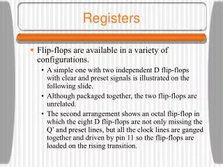
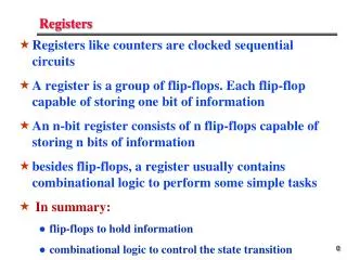
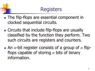
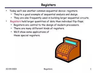
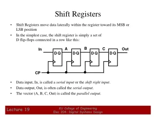
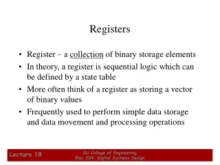
Basic shift register functions • A register is a digital circuit with basic functions: • Data storage and • Data movement • The storage capacity of a register is the total number of bits it can retain. • Shift registers consists of an arrangement of flips-flops • Each stage (flip-flop) in a shift register represents one bit of storage capacity. • The shifting capacity permits the movement of data from stage to stage within the register or into or out of the register upon application of clock pulses. • The basic difference between a register and a counter is that a register has no specified sequence of states, except in certain very specialized applications. • A register is used solely for storing and shifting data
Serial in/serial out shift registers • It accepts data serially, one bit at a time on a single line, and produces the sorted information on its output also in a serial form
Serial in/serial out shift registers • 4 bit register • It needs 4 clock pulses to store 4 bits • Example: • Illustrate entry of the 4 bits 1010 into the register. • Illustrate serially shifting the 4 bits out of the register, i.e. clearing the register.
Example: Show the states of the 5-bit shift register for the specified data input and clock waveforms. The registered is initially cleared.
Serial in/parallel out shift registers • Data bits are entered serially as illustrated before • Once the data are stored, the output of each stage is available on its output line.
Serial in/parallel out shift registers • 4-bit register
Serial in/parallel out shift registers • Example: Show the state of the 4-bit register foe the data input and clock waveforms. The register initially contains all 1s.
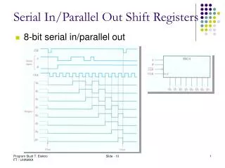
Serial In/Parallel Out Shift Registers • 8-bit serial in/parallel out
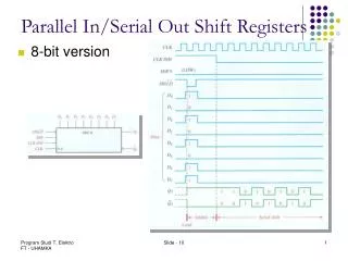
Parallel In/Serial Out Shift Registers • The bits are entered simultaneously into their respective stages. • The serial output appears bit by bit per clock pulse. • To store 4 bits, we need 1 clock pulse • To shift them out them, we need another 3 clock pulses. • 4-bit parallel in/serial out
Parallel In/Serial Out Shift Registers 4-bit parallel in/serial out
Parallel In/Parallel Out Shift Registers • The bits are entered simultaneously into their respective stages. • Immediately, the bits appear on the parallel outputs. 4-bit version
Parallel In/Parallel Out Shift Registers • 4-bit version
Parallel In/Parallel Out Shift Registers • 4-bit version
Bidirectional Shift Register • A bidirectional shift register is one in which the data can be shifted either left or right. 4-bit version
End of the slides These slides are based on Digital Fundamentals 9th ed. By Thomas Floyd