FLUOROSCOPY
FLUOROSCOPY. X-RAYS IN MOTION “Viewing dynamic studies of the human body”. HISTORY. Thomas Edison, 1896 Screen (zinc-cadmium sulfide) placed over patient’s body in x-ray beam Radiologist looked directly at screen Red goggles-30 minutes before exam 1950 image intensifiers developed.

FLUOROSCOPY
E N D
Presentation Transcript
FLUOROSCOPY X-RAYS IN MOTION “Viewing dynamic studies of the human body”
HISTORY • Thomas Edison, 1896 • Screen (zinc-cadmium sulfide) placed over patient’s body in x-ray beam • Radiologist looked directly at screen • Red goggles-30 minutes before exam • 1950 image intensifiers developed
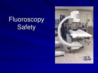
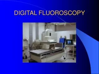
PRESENTLY…. • Fluoro viewed at same level of brightness as radiographs (100-100 lux) • X-ray tube under table/over table or in c-arm • Image intensifier above patient in carriage • Carriage also has the power drive control, spot film selection and tube shutters
RED GOGGLES?The eye • Light passes thru the cornea • Between the cornea and lens is iris • Iris acts as a diaphragm • Contracts in bright, dilates in dark
Light hits lens which focuses the light onto the retina where the cones and rods await • Cones- central • Rods - periphery
Sensitive to low light Used in night vision (scotopic vision) Dims objects seen better peripherally Color blind Do not perceive detail Less sensitive to light (threshold of 100 lux) Will respond to bright light Daylight vision (phototopic vision) Perceive color, differences in brightness Perceive fine detail RODS CONES
IN FLUOROSCOPY • The winner is…… • CONES!!
FLUORO X-RAY TUBES • Operate at .5 to 5mA. Why do they operate at such low mA stations? • They are designed to operate for a longer period of time with higher kVp for longer scale contrast. • kVp dependent on body section • kVp and mA can be controlled to select image brightness • Maintaining (automatic) of the brightness us called ABC or ABS or AGC (control,stabilization gain control)
Fluoro X-ray Tubes • Fixed…may be mounted no closer than 15 inches or 38 cm to patient • Mobile may be brought no closer than 12 inches or 30 cm to patient
IMAGE INTENSIFIER RECEIVE REMNANT X-RAY BEAM, CONVERT IT TO LIGHT…INCREASE THE LIGHT INTENSITY 5000-30,000 TIMES
THE SEQUENCE • Beam exits the patient • Hits the input phosphore(cesium iodide CsI tightly packed needles…produce excellent spatial resolution) • Converts x-rays to visible light
The sequence cont. • Hits photocathode (Cesium and antimony components) • Emits electrons when struck by light (photoemission)
The sequence cont • The potential difference within the image intensifier tube is a constant 25,000 volts • Electrons are accelerated to anode • Anode is a circular plate with hole for electrons to go thru. • Hits output phosphor which interact with electrons and produce light
The Electron Path • MUST BE FOCUSED FOR ACCURATE IMAGE PATTERN • Electrostatic lenses (focusing devices) • Accelerate and focus electron beam • “The engineering aspect of maintaining proper electron travel is called electron optics”
Continuing the sequence • Electrons hit output phosphor (zinc cadmium sulfide) with high kinetic energy producing an increased amount of light • Each photoelectron at the output phosphor has 50-75 more light photons
FLUX GAIN • Ratio of number of light photons at the output phosphor to the number of x-rays at the input phosphor • Flux gain = # of output light photon # of input x-ray photons
Ratio of the square of the diameter of the input phosphor to the square of the diameter of the output phosphor OR # of electrons produces at large input screen ( 6 inches) squared, compressed into the area of small output screen ( 1 inch) squared Try the math 6 inches squared = 36 1 inch squared = 1 Minification gain = 36 MINIFICATION GAIN
BRIGHTNESS GAIN • Minification gain x flux gain • Increases illumination level of an image • Ratio of the intensity of the illumination ot the output phosphor to the radiation intensity at the input phosphor • Brightness gain of 5000-30,000 • Maintaining (automatic) of the brightness us called ABC or ABS or AGC (control,stabilization gain control)
CONVERSION FACTOR • Ratio of intensity of illumination at the output phosphor (measured in Candela per meter squared) to the radiation intensity at the input phosphor (mR per sec) • Cd/mr squared mr/s
MULTIFIELD IMAGE INTENSIFICATIONAllows focal point change to reduce field of view and magnify the image
Some facts about multifield image intensifiers • Standard component on most machines • Always built in in digital units • Most popular is 25/17 • Trifield tubes are 25/17/12 or 23/15/10
MULTIFIELD IMAGE INTENSIFICATION • Numeric dimensions refer to the input phosphor (25/17) • Smaller dimension (25/17) result in magnified images • At 25-all photoelectrons are accelerated to output phosphor
MULTIFIELD IMAGE INTENSIFICATION • Smaller dimension – voltage of focusing lenses is increased • Electron focal spot moves away from the output. • Only the electrons from the center of input strike the output
Only central region of input is used Spatial resolution is better (think of it as the umbra!) Lower noise, higher contrast resolution Minification gain is reduced = dimmer image To compensate must increase mA Increase patient dose PROS CONS
COMING SOON • Coupling (Vidicon, Plumbicon) • Fiber Optics • Lens coupling • Beam splitting • Modulation • Size of the video signal directly proportion to the light intensity received by x-ray tube. The signal received by the TV tube is modulated
Image recording • Cassette loaded spot film • When recording image, the radiographic mA goes from a low mA to high mA. Why? • Photospot camera • Patient dose increases with size of film
DIGITAL FLUOROSCOPY • Bushong, Chapter 27 pgs 437-441 • Reference: Chapter 12, Fauber pg 302-303 to include figure 12-6
QUESTION Why is it easy to convert a conventional fluoro unit to a digital one?
Facts about digital fluoro • Image acquisition is faster • Can post process • Similar equipment to a conventional fluoro room except • two monitors • Operates in radiographic mode
DF and radiographic mode • Hundreds of mA vs 5 mA • Due to the high generator required for DF • the x-ray beam is pulsed progressive fluoroscopy
PULSED PROGRESSIVE FLUOROSCOPY • Generator can be switched on and off rapidly • Interrogation time • Tube switched on and meets selected levels of kVp and mA • Extinction time • Time required for the tube to be switched off • Each must have times of less than one 1 ms.
CCD • Instead of a vidicom or plumbicom (see figure 27-8, pg 440 Bushong) • Discuss Box 27-1 on pg 441
FPIR (pg 440-442) • Flat panel Image receptor • Replacing CCD’s • Made of cesium Iodide pixel detectors • Lighter, smaller than image intensifiers • No cassette needed
FPIR CONT. • Improvement to image as the spatial resolution is uniform and distortion free • High DQE • Improved contrast • Rectangular image • See page 442 Box 27-2