Download
1 / 48
480 likes | 611 Views
System Integration and QA. Elder Matias Canadian Light Source University of Saskatchewan. Agenda. The CLS Facility System Engineering Approach Control System Design Instrumentation Design Conclusion. Where is Saskatoon?. Why Saskatoon?.

E N D
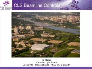
System Integration and QA Elder Matias Canadian Light Source University of Saskatchewan
Agenda • The CLS Facility • System Engineering Approach • Control System Design • Instrumentation Design • Conclusion
Why Saskatoon? • 1964 Saskatchewan Accelerator Lab (SAL) was established for chemistry and nuclear physics research. • Saskatoon was chosen for the CLS due to existing complement of staff and facilities
100 KSRS (124m) ANKA SPEAR3 (240m) TLS-I CLS (171m) PLS MAX-II TLS-II 10 LSB Super-SOR BOOMERANG APS Emittance(nm·rad) ESRF ELETTRA BESSY-II Spring-8 SLS(240m) ALS ESRF SOLEIL(2006,354m) ELETTRA APS Spring-8 DIAMOND(2007,562m) NSLS-II 1 0 1 2 3 4 5 6 7 8 9 Energy(GeV) What are the CLS Objectives? • 170.88 m circumference • 2.9 GeV DBA lattice with 12-fold period • Nominal Tune: • x = 10.22 • y = 3.26 • Eloss per turn: > 0.876 MeV • Bend magnet radiation: • c = 1.6 Å • Ec = 7.6 keV • x = 18.1 nm•rad • Damping times: • x = 2.4 ms, y = 3.8 ms, E = 2.7 ms • ~10 mm bunch length
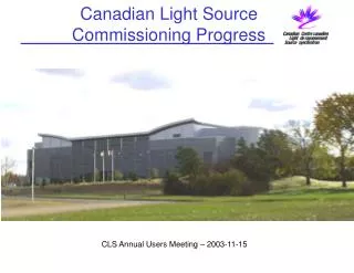
The CLS Project • 1999-2004 • LTB1 (Transfer Line) • BR1 (Booster Ring) • BTS1 (Transfer Line) • SR1 (Storage Ring) • Diagnostic Beamlines • OSR • XSR • Scientific Beamline • SGM, PGM (Soft-X-ray) • SM • Mid IR, Far IR • HXMA (Hard X-ray) • CMCF (PX) • 2005- • Additional 7 beamlines • 2008- • Additional 6 beamlines
CLS Project Structure • Nine Work packages: • 0. Administrative Support and Project Planning • 1. Linac Refurbishment • 2. LTB – Transfer Line to Booster • 3. BR1 – Booster Ring • 4. BTS – Transfer Line to Storage Ring • 5. SR1 – Storage Ring • 6. Phase 1 Beamlines • 7. System Integration (Controls and Diagnostics) • 8. Facility (Building and Mechanical Services)
Collaborate and Reuse • Internal Collaboration/Reuse • Standardize equipment where it does not impact scientific capability to reduce development and maintenance time • Standardize Design Approach Toolkits and Methods across beamlines and accelerator • Common toolkit and tools across all projects • External Collaboration/Reuse • Based on analysis of requirements versus available systems e.g., EPICS, RTEMS, IRMIS, ScienceStudio
Design Package • A Design Package Includes: • PFD Drawings used by Mechanical Engineering to capture system layout and critical parameters, e.g., water flow rates etc. • P&ID Drawings used by Controls to define the inputs and outputs of the system and basic relationships • Partially based on American Instrumentation Society • Wiring diagrams • Requirements Document (Developed as required) • PLC and EPICS Software
Drawings • All Drawings have a unique drawing number • AutoCAD, Inventor, Eagle, Visio • Draft Drawings have letter numbering • Approved Drawings Alpha Numbering • Drawings Review and Approval Process • Sketches have Sketch numbers • As-built captured on master print • Master print in control room, updated by CAD as time permits
Change Control (Major Changes) • Major Changes handled through ECR/ECO Process • Minor changes handled through MKS Integrity database
Change Control (Minor Changes) • Central Database • MKS IntegrityMKS Source • Includes source control • Web and IDE Based • Implements the concept of “Sandboxes” and “Change Packages” • Exploring options for using: • MKS Requirements • MKS Deploy
Design for Maintainability • Design systems for the long term • Phase out and replace older equipment whenchanging standards • Examples • Replacing 68360 IOCwith Moxa IOCs • Linac upgrade • PS upgrade
Time Content Conventional Software EngineeringUsed for Web Services Projects Slide prepared by IBM for CLS CANARIE Project
Safety Critical Software • Applications: • lockup system (ACIS) • Oxygen monitoring • BMIT human studies (under development) • IEC 61508 – SIL 3 based system • Subject to CNSC Approval • Siemens S7/400 F • Redundant Second Chain • Fail-safe design • Independent Verification • ALARP Hazard Analysis
Hazard Analysis • Hutch is not Searched and Secured Prior to Beam Operation Analysis:The level of radiation present in a beamline hutch when the safety shutters are open is of a potentially lethal level and can not be easily detected by a worker in the hutch, it is conceivable that multiple workers could be harmed. To mitigate this hazard it is necessary to introduce an E/E/PE system (called the Access Control and Interlock System (ACIS)) that requires each hutch to be search and secured prior to beam operation through a lockup sequence. • Mitigation:
Control System Design Principles • System design based on highly distributed control. • Extensive use of single board computers (originally used in SAL). • Target lifetime of 15+ years. • Data communication over Ethernet when possible. • System must be user-friendly. • The accelerator and beamline systems must be maintainable by a small team. • Reliability and availability of beam are critical to the success of the facility. • Building an open source control system was not the initial goal, it was the outcome. • Accelerator complex must be complete by Dec. 2003 and the first phase of beamlines by Dec. 2004. The project must come in on budget.
Distributed Control Systems • The options: (1) EPICS or (2) Isagraph/Virgo. • EPICS was selected, since it had: • large built up accelerator and beamline user community; • availability of suitable drivers and utilities; • credibility with the CLS user community; and • good design. • EPICS Extensions selected include: • EDM, • Accelerator Toolbox, • Gateway and • Data Archiver. • EPICS extensions that were locally developed: • assortment of drivers, • IOC Auto-Save-Restore, • simple beamline scanning program, and • SQL Alarm Management Database.
Control Room/Areas • Quad Headed Scientific Linux workstations in the accelerator control room and Dual Headed workstations on the beamlines. • Scientific Linux (CERN/Fermilab) (https://www.scientificlinux.org/) • Human Factors Engineering • EPICS Tools • EDM (Display Manager) • Strip Tool (Data Trending) • CLS Specific • Audio Alarm Annunciation • Legacy hard-wired controls from older Linac Equipment
Selecting a Real-time OS • The Options: (1) RTEMS and (2) VxWorks. • RTEMS was selected, since it had: • good experience from SAL, • additional flexibility with single board computers, and • high level of reliability. • IOCs are CLS/SIL embedded controllers (approx 150) based on the MC68360 25 MHz. Processor. Pros and Cons: • No dynamically loaded libraries; must be linked prior to download. • Large number of IOCs (separation of function but more points of failure) Note: EROCS now replaced with MOXA Linux computers.
Moxa • Transitioning from SAL single-board-computers to MOXA based IOC • Linux based • EPICS with the asyn driver and older CLS serial drivers • Used extensively for RS-232/422/485
VME • VME hardware connected to a Linux PC. • SIS1100 PCI card <-> fiber optic link <-> SIS3100 VME module • Maps VME backplane to IOC memory. • Advantages: • PC can be physically separated from VME crate. • More than one VME crate per PC. • Multiple applications can access the same crate. • High throughput 25 to 80 Mbytes/sec block transfer. • Using RTEMS Real-time operating system.(www.rtems.org)
Online scripting environment • The options: (1) Matlab, (2) SciLab, or (3) root. • Matlab was selected primarily because of the availability of the accelerator toolbox and staff experience. • Matlab is commercial, the accelerator toolbox is open source. • Software originates from ALS and SPEAR III. • Augmented with other CLS specific utilities. • Also being used as a commissioning tool for beamlines. • Special care is required to maintain consistency with other parts of the control system.
Timing System • Provides fiber optic signal distribution of triggers. • VXI based hardware • IOC running EPICS on RTEMS. • OperatorInterface implemented using Glade. • Glade wasselected forthe table andfile handlingcapabilities.
Implementation Strategy • Single board computers (EPICS/RTEMS) used for: • stepper motors, • power supply control, • vacuum equipment monitoring, • radiation monitors, and • other RS-232 devices. • PLC hardware/software used for machine protection. • Industrial PCs with VME used for diagnostics. • Linux servers used for high-level control, network services and EPICS/PLC interface. • MOXA RS-232 Computers
EPICS Channel Access Protocol Profibus TCP/IP CA CA IOC Operator Workstation User Applications Siemens S7/300 PLC CA Touch Panels Modbus TCP/IP CA IOC Telemecanique Momentum PLC CA State Machine Engine CA GPIB IOC CA IOC CA RS-232 VME CA IOC Single Board Computer
Linac Controls • Machine Protection • Telemecanique Momentum PLC • RF • Hardwired + Telemecanique Momentum PLC • Power Supplies • Old (20+ year) power supplies upgraded (Danfysik + Brooker) • Now being replaced (IE Power + Agilent) • Diagnostics • FCT, ICT etc. (Scope) • Spill Monitors (CBLM) • Pop-up Viewers (CCTV + Line Generators) • TRM (Computer based image processing) • Isolated Beam-dumps
BR1 Controls • Turn-key Danfysik booster • Machine Protection (CLS Design) • Telemecanique Momentum PLC • RF (Danfysik/ACCEL Design) • Siemens S7/300 • ANKA based electronics • ramped with trigger • Power Supplies • Danfysik (RS-232) • Ramped Power Supplies, with trigger • Kickers PPT • Diagnostics • Bergoz BPMs • Bergoz FCT, ICT, PCT • Bergoz Spill Monitors • Striplines • CLS CBLM Spill Monitors • CLS Spill Monitors • Synchrotron Light Monitors (3) • Pop-up viewers (4)
SR1 RF • Amplifier (Thales) • Siemens S7/400 • Cavity (ACCEL) • Siemens S7/300 • Low Level RF (CLS) • Siemens S7/300 • Cryo Plant (Linde) • Siemens S7/400
SR1 Machine Protection • Vacuum, Water Flow, Thermal Switches • Telemecanique Momentum PLC • Vacuum Chamber Temperature • National Instruments FieldPoint (should have used Momentum) • Fast Orbit Protection • Custom electronics, • PLC provides thresholdsfor comparison • Trip when current < 10mA based on RF power
SR1 Power Supplies • IE Power • Ring Lattice Power Supplies • RS-232/485 Slow Control • Special/Custom Interfacefor Fast Correctors • Danfysik/PPT • Kicker Power Supplies • RS-485 + Trigger • Significant Time Needs to be allocated to tuning new power supplies
SR1 Diagnostics • Bergoz BPM • Bergoz PCT • CBLMs • OSR & XSR • Agilent VSA • Agilent Remote Scopes • Matlab Toolbox • Envelop Detector • Transient Recorder? • Diagnostic Kicker (under development)
BPM Electronics Selection • Studies were done on the Bergoz, and Libera Electron units • This summer we will test Libera Brilliance
Beamlines • Beamline Controls are based on the same software and hardware as the accelerator systems. • Each beamline is on a separate virtual network. • The EPICS Gateway provides links between the different networks. • Matlab is used for scripting.
UCLPcommands domain manager process User Configurable Light Paths Lightpath Accelerator controls a software virtual cross-connect that commands UCLP. In effect, CA*Net4 is treated as a single lightpath cross-connect real device real device virtual device
Mechanical Services • Telemecanique MomentumPLCs • Ring temperature stabilityrequirement +/- 0.1 C. • Geographically Distributed • Legacy Systems: • Most 1960s equipment upgradedin 2005 • Most 1980s equipment upgradedin 2004 • Limited number of systemsstill using Invensys DMS DCS
Fire Protection • Notifier System • Smoke Detectors • Laser Detection • VESDA • CO2 Near Oil RF Systems • Power Trip • Two Zones Trip • Pull Station
Electrical Services • MCC (Siemens) • SR1/BR1 - 600 V • Linac - 480V • Panels • 120 V, 208 V • Conduit used extensively • For control applications each rack cluster is on the same phase • Early morning grid adjustments were problem at times for some power supplies
Grounding • Grounding routed back to the main transformer yard • Beamline have isolated grounds, with mixed results. • Beamline have two separate transformers • Convenience (Dirty) • Isolated (Clean) • Mechanical System from a Separate Transformer