Download
1 / 41
410 likes | 465 Views
System Integration and QA. Elder Matias Canadian Light Source University of Saskatchewan. Where is Saskatoon?. Why Saskatoon?. 1964 Saskatchewan Accelerator Lab (SAL) was established for chemistry and nuclear physics research.

E N D
System Integration and QA Elder Matias Canadian Light Source University of Saskatchewan
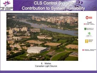
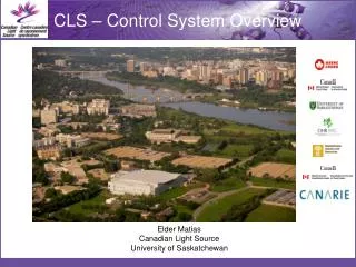
Why Saskatoon? • 1964 Saskatchewan Accelerator Lab (SAL) was established for chemistry and nuclear physics research. • Saskatoon was chosen for the CLS due to existing complement of staff and facilities
100 KSRS (124m) ANKA SPEAR3 (240m) TLS-I CLS (171m) PLS MAX-II TLS-II 10 LSB Super-SOR BOOMERANG APS Emittance(nm·rad) ESRF ELETTRA BESSY-II Spring-8 SLS(240m) ALS ESRF SOLEIL(2006,354m) ELETTRA APS Spring-8 DIAMOND(2007,562m) NSLS-II 1 0 1 2 3 4 5 6 7 8 9 Energy(GeV) What are the CLS Objectives? • 170.88 m circumference • 2.9 GeV DBA lattice with 12-fold period • Nominal Tune: • x = 10.22 • y = 3.26 • Eloss per turn: > 0.876 MeV • Bend magnet radiation: • c = 1.6 Å • Ec = 7.6 keV • x = 18.1 nm•rad • Damping times: • x = 2.4 ms, y = 3.8 ms, E = 2.7 ms • ~10 mm bunch length
The CLS Project • 1999-2004 • LTB1 (Transfer Line) • BR1 (Booster Ring) • BTS1 (Transfer Line) • SR1 (Storage Ring) • Diagnostic Beamlines • OSR • XSR • Scientific Beamline • SGM, PGM (Soft-X-ray) • SM • Mid and Far IR • HXMA (Hard X-ray) • 2005- • Additional 7 beamlines
Drawings • All Drawings have a unique drawing number • AutoCAD, Inventor, Eagle, Visio • Draft Drawings have letter numbering • Approved Drawings Alpha Numbering • Drawings Review and Approval Process • Sketches have Sketch numbers • As-built captured on master print • Master print in control room, updated by CAD as time permits
Documents • Documents • Numbered and Traceable • Under Revision Control • Review and Approval Process • Centrally Stored and Distributed
Agenda • The CLS Facility • Quality Assurance Program • System Engineering Approach • Control and Instrumentation Design
Safety Critical Software • Applications: • lockup system (ACIS) • Oxygen monitoring • BMIT human studies (under development) • IEC 61508 – SIL 3 based system • Siemens S7/400 F • Redundant Second Chain • Fail-safe design • Independent Verification
Agenda • The CLS Facility • Quality Assurance Program • System Engineering Approach • Control and Instrumentation Design
Control System Design Principles • System design based on highly distributed control. • Extensive use of single board computers (originally used in SAL). • Target lifetime of 15+ years. • Data communication over Ethernet when possible. • System must be user-friendly. • The accelerator and beamline systems must be maintainable by a small team. • Reliability and availability of beam are critical to the success of the facility. • Building an open source control system was not the initial goal, it was the outcome. • Accelerator complex must be complete by Dec. 2003 and the first phase of beamlines by Dec. 2004. The project must come in on budget.
Distributed Control Systems • The options: (1) EPICS or (2) Isagraph/Virgo. • EPICS was selected, since it had: • large built up accelerator and beamline user community; • availability of suitable drivers and utilities; • credibility with the CLS user community; and • good design. • EPICS Extensions selected include: • EDM, • Accelerator Toolbox, • Gateway and • Data Archiver. • EPICS extensions that were locally developed: • assortment of drivers, • IOC Auto-Save-Restore, • simple beamline scanning program, and • SQL Alarm Management Database.
The Operator Interface • The options: (1) Sun or (2) Linux. • Linux was selected, since it had: • better hardware availability, and • fairly equivalent reliability levels. • EPICS Extensions selected include: • EDM, • Array Display Tool, • StripTool, and • Knob Manager. • We are now starting to deploy touch screens running Linux/EDM.
Accelerator Dashboard Related displays: links to other EDM screens
Implementation • A group status PV is created to indicate the collective status of a group of components in a sub-system. Eg. PV LTB1:IOP:status gives the collective status for all the ion pumps in the LTB • The group status PV monitors all individual PVs in this group and calculate the group status. Different algorithms are used for different types of PVs. Eg. The most common algorithm finds out the highest alarm level in all the individual PVs and pass it to the group PV.
Process Screens • Some screens are done in Visio or AutoCAD then imported into EDM
Selecting a Real-time OS • The Options: (1) RTEMS and (2) VxWorks. • RTEMS was selected, since it had: • good experience from SAL, • additional flexibility with single board computers, and • high level of reliability. • IOCs are CLS/SIL embedded controllers (approx 150) based on the MC68360 25 MHz. Processor. Pros and Cons: • No dynamically loaded libraries; must be linked prior to download. • Large number of IOCs (separation of function but more points of failure) Note: EROCS now replaced with MOXA Linux computers.
Moxa • Transitioning from SAL single-board-computers to MOXA based IOC • Linux based • EPICS with the asyn driver and older CLS serial drivers • Used extensively for RS-232/422/485
VME • Using VME hardware connected to a Linux PC. • SIS1100 PCI card <-> fiber optic link <-> SIS3100 VME module • Maps VME backplane to IOC memory. • Advantages: • PC can be physically separated from VME crate. • More than one VME crate per PC. • Multiple applications can access the same crate. • High throughput 25 to 80 Mbytes/sec block transfer. • Work ongoing on RTEMS support.
Online scripting environment • The options: (1) Matlab, (2) SciLab, or (3) root. • Matlab was selected primarily because of the availability of the accelerator toolbox and staff experience. • Matlab is commercial, the accelerator toolbox is open source. • Software originates from ALS and SPEAR III. • Augmented with other CLS specific utilities. • Also being used as a commissioning tool for beamlines. • Special care is required to maintain consistency with other parts of the control system.
Timing System • Provides fiber optic signal distribution of triggers. • VXI based hardware • IOC running EPICS on RTEMS. • OperatorInterface implemented using Glade. • Glade wasselected forthe table andfile handlingcapabilities.
Implementation Strategy • Single board computers (EPICS/RTEMS) used for: • stepper motors, • power supply control, • vacuum equipment monitoring, • radiation monitors, and • other RS-232 devices. • PLC hardware/software used for machine protection. • Industrial PCs with VME used for diagnostics. • Linux servers used for high-level control, network services and EPICS/PLC interface. • MOXA RS-232 Computers
Beamlines • Beamline Controls are based on the same software and hardware as the accelerator systems. • Each beamline is on a separate virtual network. • The EPICS Gateway provides links between the different networks. • Matlab is used for scripting.
MS-SQL Server MS-Win OPI Linux OPI Linux OPI Linux Touch Panel OPI Linux Network Server (bootp, dhcp, auto restore) Linux Data Archive Server Linux Alarm Server MS-Win VLANs for: each beamline, machine control, development, office, visitors PowerEdge IOC Linux VME Crate (Reflective Memory) EROC IOC RTEMS IOC Step Controller RTEMS PS Boards IOC RTEMS EROC IOC RTEMS IOC Linux 1Gig Bridge MicroStep Field Dev. RS-232 Devices MicroStep Power Supplies Ethernet Devices PLC & GPIB Profibus PLC Motors Field Dev. Motors Magnets Field Dev. Field Dev.
Linac Controls • Machine Protection • Telemecanique Momentum PLC • RF • Hardwired + Telemecanique Momentum PLC • Power Supplies • Old (20+ year) power supplies upgraded (Danfysik + Brooker) • Now being replaced (IE Power + Agilent) • Diagnostics • FCT, ICT etc. (Scope) • Spill Monitors (CBLM) • Pop-up Viewers (CCTV + Line Generators) • TRM (Computer based image processing) • Isolated Beam-dumps
BR1 Controls • Turn-key Danfysik booster • Machine Protection (CLS Design) • Telemecanique Momentum PLC • RF (Danfysik/ACCEL Design) • Siemens S7/300 • ANKA based electronics • ramped with trigger • Power Supplies • Danfysik (RS-232) • Ramped Power Supplies, with trigger • Kickers PPT • Diagnostics • Bergoz BPMs • Bergoz FCT, ICT, PCT • Bergoz Spill Monitors • Striplines • CLS CBLM Spill Monitors • CLS Spill Monitors • Synchrotron Light Monitors (3) • Pop-up viewers (4)
SR1 Machine Protection • Vacuum, Water Flow, Thermal Switches • Telemecanique Momentum PLC • Vacuum Chamber Temperature • National Instruments FieldPoint (should have used Momentum) • Fast Orbit Protection • Custom electronics, • PLC provides thresholdsfor comparison • Trip when current < 10mA based on RF power
SR1 RF • Amplifier (Thales) • Siemens S7/400 • Cavity (ACCEL) • Siemens S7/300 • Low Level RF (CLS) • Siemens S7/300 • Cryo Plant (Linde) • Siemens S7/400
SR1 Power Supplies • IE Power • Ring Lattice Power Supplies • RS-232/485 Slow Control • Special/Custom Interfacefor Fast Correctors • Danfysik/PPT • Kicker Power Supplies • RS-485 + Trigger • Significant Time Needs to be allocated to tuning new power supplies
SR1 Diagnostics • Bergoz BPM • Bergoz PCT • CBLMs • OSR & XSR • Agilent VSA • Agilent Remote Scopes • Matlab Toolbox • Envelop Detector • Transient Recorder? • Diagnostic Kicker (under development)
Mechanical Services • Telemecanique Momentum PLC • Geographically Distributed • 1960s equipment upgradedin 2005 • 1980s equipment upgradedin 2004 Limited legacy systemusing Invensys DMS
Fire Protection • Notifier System • Smoke Detectors • Laser Detection • VESDA • CO2 Near Oil RF Systems • Power Trip • Two Zones Trip • Pull Station
Electrical Services • MCC (Siemens) • SR1/BR1 - 600 V • Linac - 480V • Panels • 120 V, 208 V • Conduit used extensively • For control applications each rack cluster is on the same phase • Early morning grid adjustments were problem at times for some power supplies
Useful Commissioning Tools • MKS Integrity • Data Archiver • Strip Tool • Matlab Accelerator Toolbox (for storage ring)