Download
1 / 42
420 likes | 454 Views
Understand the challenges in developing a Pb-free tin finish with negligible whisker growth risk. Learn about the complexities, costs, and testing methods involved in preventing short circuits due to tin whiskers. Explore remedies and deficiencies.

E N D
Preventing Tin Whisker Growth Risk Rev A Bob Landman, Gordon Davy, Dennis Fritz LDF Coatings, LLC
Despite much effort, no one has yet developed an electroplated Pb-free tin finish that can be confidently regarded as having a negligible risk that whiskers will grow long enough to cause a short circuit. There is a growing suspicion that such a recipe may be as elusive as the philoso-pher's stone. Tin Whisker Facts
Even if a recipe to produce a tin-plated finish with a negligible whisker growth risk (WGR) were to be developed, before it could benefit manufacturers of high-reliability electronic systems, the vast majority of electronic component manu-facturers would have to adopt it. Tin Whisker Facts
For that adoption to happen, the recipe would have to entail negligible additional complexity and cost over present practices, since component manufacturers have not discerned a demand for it from their pri-mary market. Tin Whisker Facts
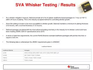
Even if a recipe to produce an inexpensive tin-plated finish with a negligible WGR were to be universally adopted by component manufacturers, despite much effort no one has yet even proposed a test method that, for a given batch of purchased components, could confirm that the manufacturer had without error followed the recipe. There is a growing suspicion that such a test method may also be as elusive as the philosopher's stone. Tin Whisker Facts Rev A – The presence of gold, antimony or germanium could be verified by XRF.
Even if a test method to confirm that a given tin finish had a negligible WGR were to be developed, it would necessarily be more complex and time-consuming than X-ray fluorescence, and hence, with few if any exceptions, impractical to use for screening purchased components. Tin Whisker Facts Rev A – XRF will find gold, antimony, and germanium in tin.
In addition to the unavoidable WGR asso-ciated with the use of commercial compo-nents, there is an unavoidable WGR asso-ciated with the use of COTS assemblies, which may also incorporate a Pb-free tin-rich solder (e.g., SAC) and a Pb-free tin-rich board finish (e.g., immersion tin). Tin Whisker Facts
Despite the best efforts of all the king's horses and all the king's men, until the prohibition on the use of Pb in electronics is lifted, electronic assemblies that incor-porate Pb-free tin will continue to pose a significant WGR (i.e., forever). Tin Whisker Facts – Summary
Even where a tin-lead termination finish is available for a desired component, its procurement often entails a significantly higher price and a significant delay. WGR Remedy Deficiencies
Replacing tin with tin-lead (i.e., by dipping or replating) is expensive; also, dipping component terminations in molten solder introduces other risks – heat and handling damage that result in latent failure modes that escape detection. WGR Remedy Deficiencies Rev A – Testing in 2003-2005 for latent failure modes on robotically solder-dipped components of various package styles indicated no heat damage.
Depending on finish replacement during soldering (i.e., based on termination shape and size) at best can only apply to a subset of all components used on an assembly. WGR Remedy Deficiencies Rev A – Only a small fraction of components can be regarded as “self-mitigating.”
Scrubbing a bill of material to identify each component that has a significant WGR is expensive and subject to mistakes. WGR Remedy Deficiencies
Screening lots of received components to catch those with Pb-free tin plating (wrongly ordered or wrongly shipped) is expensive and subject to mistakes. WGR Remedy Deficiencies
For COTS assemblies, the above means are not just impractical. They are impossible. WGR Remedy Deficiencies Rev A – Most high-reliability systems include COTS assemblies (e.g., single-board computers, power supplies). Exceptions: missiles, space hardware.
Because some whiskers soon penetrate the most widely used conformal coat-ings, these coatings at best only reduce (mitigate) WGR. WGR Remedy Deficiencies Rev A – A coating is only required to prevent penetration from the outside.
Commercial conformal coating applica-tion processes result in regions with inadequate coverage (too thin or miss-ing entirely). WGR Remedy Deficiencies • Rev A – • Commercial application is primarily by spraying. Multiple spray heads and multiple applications can be used to reduce pin holes and shadowing. • Commercial formulations are intended to prevent dendritic growth between adjacent metalizations on a board. Getting adequate coverage along sharp edges of rectangular terminations requires adding a thixotrope.
No one has yet developed a practical screening method to reveal regions with inadequate conformal coating coverage, which may be quite small but quite numerous. WGR Remedy Deficiencies A UV-fluorescing dye can be used as a rough guide to presence/absence, but not for gauging thickness. Cross sectioning is useful for process evalu-ation, but not process monitoring (destructive, too slow).
Even with a process/material combina-tion that ensures adequate coverage everywhere, even the best conformal coating, being a polymer, has relevant physical properties (in particular, adhe-sion and penetrability) that vary signifi-cantly within the service environment and lifetime. WGR Remedy Deficiencies
No one has yet demonstrated how effectively any polymer coating would reduce WGR over the full range of temperature (-55° to +125° C) and humidity (0 to 100%), for the full intended service life (30 years) of a high-reliability electronic system. WGR Remedy Deficiencies
Moral – if ignoring the risk is knowing and deliberate:Counting on the customer's difficulty proving that a whisker was the cause of a given malfunction. Hazards of Ignoring WGR
Whether knowingly or unknowingly (i.e., whether the neglect is deliberate or tacit):A field failure rate too large to conceal the cause from the customer. If this occurs, it entails huge costs and delays. In seeking a remedy, the manufacturer must in many cases engage outside expertise. Frequency of occurrence is unknown because victims conceal most cases. Victims’ failure to reveal → more victims (i.e., due to managers’ unawareness of, or underestimating the magnitude of, the risk). Hazards of Ignoring WGR
It shall be: Safe “First, do no harm” (Hippocrates, 4th cent. B.C.) Effective “A little dab’ll do ya” (Brylcreem) Practical “Best thing since sliced bread” Acceptance Requirementsfor Any Remedy
Find a TW prevention means more practical than component termination finish replacement Applicable to a soldered assembly Able to protect from TW shorts permanently Must cap Sn with a TW-impenetrable material How about a non-capping process to overcomePb-free Sn’s TW proclivity? TheTW Prevention Challenge
Ceramic Applied layer-by-layer in a vacuum system 200 nm cap unpenetrated > 1 yr. Polymer Thixotropic for complete coverage Resilient rather than impenetrable Substitute for conformal coating Metal Deposited selectively on Sn and other metals 1. TW tents the cap 2. Cap buckles the TW Three Possible Capping Means
It shall be: Safe Capping process shall not harm the assembly Cap’s impenetrability shall survive temp cycling, RH, and time Process and cap material shall be safe for people Effective Process shall give consistent results within wide margins Cap shall prevent, not retard, TW penetration Cap’s TW prevention shall be permanent Practical Process shall be quick, easy, inexpensive, and integrate well into assembly/test process flow Acceptance Requirements for TW Capping Process/Product Still a long way from an acceptance test specification
Test or analyze? If test, What kind of tests are appropriate for this type of cap? Test severity and duration? If analysis, what are the analyst’s qualifications? What does it take to pass the test? How confident can you be that passing each test = meeting the corresponding requirement? What is the baseline? Who decides? Next Steps to a Cap ProcessAcceptance Test Specification
TWmitigation meansnow in useare marginal this mitigates the need for proof Do you really need to wait for 30 years to show no TWs? Where’s the proof that your TW mitigationmeansis adequate? Baseline – Is this prevention meansbetter than what we’re doing now? PreventionMitigation Perspective on Proving vs. Convincing – ofPrevention Means’ Effectiveness Preventionreplaces, not augments,mitigation
Apply process to assembly, not components NoMitigation BOM scrubbing Receiving inspection for Pb-free Sn Auditing mitigationactivity for compliance/effectiveness Cap and process are safe for product and people Cap and process are effective Permanently suppresses TW growth Prevents, not mitigates, TW risk for all assy’s, incl. COTS Must settle for supporting data and rigorous analysis Cap process is practical Fast Low cost of ownership and labor Non-sole source Integrates easily into existing product flow New topic – Process Req’ts for IdealTW Prevention Capping Process
Metal cap process mustbeselective Vapor deposition – no way! You gotta give your baby a bath! Does it get wet after soldering? Wet with what? Wet’s wrong with that? How can you metal-cap the Sn and notthe assembly’s insulating surfaces?
Three options could be considered, but only one is OK Electrochemical (electroplated) All Sn surfaces must be electrically connected Immersion (replacement) Too thin Electroless (autocatalytic) fills the bill Surface preparation and rinsing are routine Deposition is Yes or No, Go or No-Go Go on Sn (and on most metals) No-Go (not verrry slooow!) on all insulators → Ni and Pd among TW-impenetrable metals Mask just once Surfaces not to be capped = surfaces not to be conformally coated Slow go No go Selective Metal Cap Layer ProcessFor Coating Sn on Assemblies
Are you crazy? I’d never put any assembly of mine in a plating bath!!! Why not? You do remove flux by aqueous cleaning, right? Are you “data-driven” or “intuition-driven”? But, but – that’s never been done before!!! And your point? Will all the Sn plate? Electroless plating a long-established industry practice Sn’s native oxide coating only 2-3 nm, easily dissolved It’s chemistry, not magic If it’s Sn and it’s clean, why wouldn’t it? Reactions
Flow diagram shows added and eliminated steps Scale layout drawing for each tank New topic – Practical? How does this all work?
Insert Cap Process Here Inspect, Test Inspect, Test Inspect, Test Inspect, Test Expensive Clean, Mask Mask Remove Masking Remove Masking Assemble, Solder, Clean Assemble, Solder, Clean Conf. Coat Conf. Coat OK OK Components Boards, Paste Components Boards, Paste OK OK Hard to audit Inspect Comp’s for Sn Prepare &Work to LFCP* Scrub BOM† * Lead-free control plan † Bill of materials Inexpensive Easy to audit Clean Clean Clean, Dry Immerse in Cap Sol’n TW Mitigationvs. Prevention Capping Conventional Process – TW Mitigation, notPrevention Mitigation Process Differences in Color Capping New TW-Prevention Metal-Capping ProcessCeramic- and polymer-capping processes similar
Dry station Electrolessdeposition Top View Alkalineclean Acidicclean Rinse 14 in. Work flow Side View 10 in. To drain Water in To drain Water in To drain Water in 10 in.(typ) Electroless Plating System Layout Scale Model Cascade rinse Rinse
Proof of Concept – April 2010 • Effective: Has Ni capped the Sn? • Yes. First evidences: micro-bubbles, then altered appearance on Cu • Thickness: 5-min. electroless deposition XRF: 2.9 ± 0.2 µm Ni, 2 assemblies, 3 locations ea. • Effective: Have TWs penetrated? • None seen in > 1 year • Safe: Does the ass’y still work? • Yes, after more than 10X the plating time to get a 2-3 µm Ni cap
Effective? - Ni Applied To This HL Instruments Commercial Product
Every assembly still functions after immersion No failures Assembly is clean: C3: In steam extract of surface, with 10 VDC across || electrodes, measure time to 500 µA Ion Chromatography: In steam extract of surface, measure anion (e.g., Cl-, SO4=) concentration SIR: After 1-month THB, measure surface insulation resistance on “umpire” assembly New topic – Safe? Is the Metal-Capping Process Safe? Foresite results: “Well above J-STD-001 requirements”
Our thanks to Terry Munson High-purity 130°C steam in Extractionchamber Specimen0.1 in2 Procedure At selected site, do this 9X: AspirationPathway Substrate with|| electrodes 300-msec steam 20-sec soak 2-sec aspirate & collect ExtractCollectionChamber Yields ~ 2½ cm3 extract Apply 10 VDC across|| electrodes Measure time to 500 µA, else stop at 3 minutes www.Residues.com “Clean” ≡ > 60 sec. C3 Test Cell Critical Contamination → Control
Cl - Br - NO2- NO3- PO4= SO4= WOA Ion Chromatography Weak organic acids ↑ Maximum observed reading (normalized to Foresite limits) 1.0 0.8 www.Residues.com 0.6 0.4 0.2 0.0 Cl- Br- NO2- NO3- PO4= SO4= WOA Ion species Foresite Contamination Test Results C3 time to 500 µA > 60 sec? All sites timed out at 3 minutes SIR – Surface Insulation Resistance Minimum > 10X the 108-ohm Requirement Our thanks to Terry Munson
Prevention now easier than mitigation Three capping concepts for assemblies A ceramic, 200 nm impenetrable A polymer, designed to thickly cover all surfaces Selective metal cap Not a new process Novelty is its application to assemblies instead of bare board 50 nm Ni, Pd, AuSn2impenetrable Any of these processesenables abandoning mitigation You’re delivering hardware with a known failure mode Hoping that TWs puncturing conformal coat won’t short Now you can increase your hardware’s reliability If you believecapping prevents TW penetration If your management believes capping prevents TW penetration If your customer believes capping prevents TW penetration Conclusions
Safe ? No loss of function on capped assemblies Foresite data ordinary rinsing gets it clean Effective ? Some metals preventTW penetration permanently For Ni, θNi≈ 35 nm Safety margin for 1-µm cap: 1½ orders of magnitude Practical ? Time for 1-µm cap: 2-3 minutes Close match to description of IdealTW-prevention capping process Conclusions – Metal Cap Process m