Simple Processor Control Unit
Simple Processor Control Unit. Instructor: Oluwayomi Adamo Digital Systems Design. Control Unit. Design a control unit for picking up instructions from memory address given by the program counter (PC). Interpret the instruction, Fetch the operands and feed them to the ALU,

Simple Processor Control Unit
E N D
Presentation Transcript
Simple ProcessorControl Unit Instructor: Oluwayomi Adamo Digital Systems Design
Control Unit • Design a control unit for picking up instructions from memory address given by the program counter (PC). • Interpret the instruction, • Fetch the operands and feed them to the ALU, • Store the result in destination registers • Load the pc with destination address in case of branch instruction, • Contents of destination will be forwarded to the LED or 7 segment display for display.
Sample Instructions Register Instruction 01001011 Branch Instruction 11100011 Halt and I/O Instruction 11001011 11000110
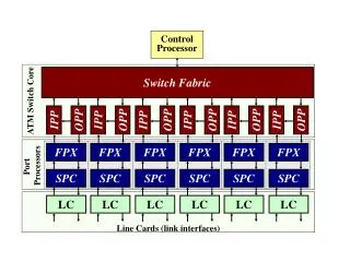
CONT UNIT D MUX CC OP RCA MUX A MUX ALU MUX PC MEM REG 0 OR1 SRC DST MUX B MUX DMUXA SWICTH 000G 4 BITS DISPLAY
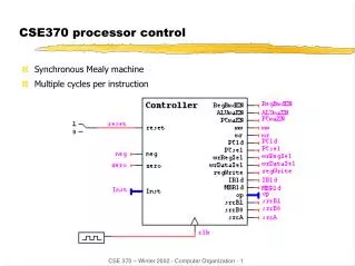
Control Unit • The control unit is like computer’s traffic cop. • It coordinates and controls all operations occurring within the processor. • The control unit does not input, output, process, or store data, • it initiates and controls the sequence of these operations. • Controls Data Movements in an Operational Circuit by Switching Multiplexers and Enabling or Disabling Resources • Follows Some ‘Program’ or Schedule • Often Implemented as Finite State Machine or collection of Finite State Machines
Control Unit as a Finite State Machine (FSM) (Contd.) • Any Circuit with Memory could be called a Finite State Machine • Even computers can be viewed as huge FSMs • Design of FSMs Involves • Defining states • Defining transitions between states • Optimization / minimization • Above Approach Is Practical for Small FSMs Only
State Machine Model input Combinational logic pr_state nx_state Sequential logic rst clock
Finite State Machine - Moore • Output Is a Function of a Present State Only • TYPE state IS (S0, S1, S2); • SIGNAL Moore_state: state; • U_Moore: PROCESS (clock, reset) • BEGIN • IF(reset = ‘1’) THEN • Moore_state <= S0; • ELSIF (clock = ‘1’ AND clock’event) THEN • CASE Moore_state IS • WHEN S0 => • IF input = ‘1’ THEN • Moore_state <= S1; • ELSE • Moore_state <= S0; • END IF; reset
Moore • WHEN S1 => • IF input = ‘0’ THEN • Moore_state <= S2; • ELSE • Moore_state <= S1; • END IF; • WHEN S2 => • IF input = ‘0’ THEN • Moore_state <= S0; • ELSE • Moore_state <= S1; • END IF; • END CASE; • END IF; • END PROCESS; • Output <= ‘1’ WHEN Moore_state = S2 ELSE ‘0’;
Finite State Machine - Mealy Output Is a Function of a Present State and Inputs • TYPE state IS (S0, S1); • SIGNAL Mealy_state: state; • U_Mealy: PROCESS(clock, reset) • BEGIN • IF(reset = ‘1’) THEN • Mealy_state <= S0; • ELSIF (clock = ‘1’ AND clock’event) THEN • CASE Mealy_state IS • WHEN S0 => • IF input = ‘1’ THEN • Mealy_state <= S1; • ELSE • Mealy_state <= S0; • END IF;
Finite State Machine – Mealy (contd.) • WHEN S1 => • IF input = ‘0’ THEN • Mealy_state <= S0; • ELSE • Mealy_state <= S1; • END IF; • END CASE; • END IF; • END PROCESS; • Output <= ‘1’ WHEN (Mealy_state = S1 AND input = ‘0’) ELSE ‘0’;
Control Unit as a Finite State Machine (FSM) • Fetch -> Decode -> Execute Fetch Sequence • t1: MAR <- (PC) • t2: MBR <- (memory) • PC <- (PC) +1 • t3: IR <- (MBR) • (tx = time unit/clock cycle)