Simple Processor Control Unit
Simple Processor Control Unit. Instructor: Oluwayomi Adamo Digital Systems Design. Objective. Design a simple processor , capable of picking up data from a switch register, Operate the switch register using manually, Display output using LEDs or seven segment display,


Simple Processor Control Unit
E N D
Presentation Transcript
Simple ProcessorControl Unit Instructor: Oluwayomi Adamo Digital Systems Design
Objective • Design a simple processor , • capable of picking up data from a switch register, • Operate the switch register using manually, • Display output using LEDs or seven segment display, • Perform basic operations such as add, subtract, multiply and divide as well as data movement. • Implement the processor in hardware, • Test your implementation using basic set of instruction you designed.
Questions to Answer • What is the System Requirement? • What are functional blocks required? • What is the size of your instructions? • Types of Instructions to design: • Data handling and manipulation (add, sub, increment, and clear etc.) • Branch instructions • Input and Output
Questions to Answer (contd.) • Draw a block diagram of your simple processor, • The block diagram should show the interconnection of different registers, modules and control unit. • Sample instructions for testing, • Control signal needed for your processor, inputs and outputs needed. • Inputs and outputs with respect to the FPGA used for implementation.
Questions to Answer (Tasks) • Design a control unit for picking up instructions from memory address given by the program counter (PC). • Interpret the instruction, • Fetch the operands and feed them to the ALU, • Store the result in destination registers • Load the pc with destination address in case of branch instruction, • Contents of destination will be forwarded to the LED or 7 segment display for display.
Sample Instructions Register Instruction 01001011 Branch Instruction 11100011 Halt and I/O Instruction 11001011 11000110
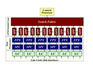
Diagram of Simple Processor • To be drawn in class
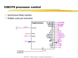
Control Unit • The control unit is like computer’s traffic cop. • It coordinates and controls all operations occurring within the processor. • The control unit does not input, output, process, or store data, • it initiates and controls the sequence of these operations. • Controls Data Movements in an Operational Circuit by Switching Multiplexers and Enabling or Disabling Resources • Follows Some ‘Program’ or Schedule • Often Implemented as Finite State Machine or collection of Finite State Machines
Control Unit as a Finite State Machine (FSM) (Contd.) • Any Circuit with Memory could be called a Finite State Machine • Even computers can be viewed as huge FSMs • Design of FSMs Involves • Defining states • Defining transitions between states • Optimization / minimization • Above Approach Is Practical for Small FSMs Only
Finite State Machine - Moore • Output Is a Function of a Present State Only • TYPE state IS (S0, S1, S2); • SIGNAL Moore_state: state; • U_Moore: PROCESS (clock, reset) • BEGIN • IF(reset = ‘1’) THEN • Moore_state <= S0; • ELSIF (clock = ‘1’ AND clock’event) THEN • CASE Moore_state IS • WHEN S0 => • IF input = ‘1’ THEN • Moore_state <= S1; • ELSE • Moore_state <= S0; • END IF; reset
Moore • WHEN S1 => • IF input = ‘0’ THEN • Moore_state <= S2; • ELSE • Moore_state <= S1; • END IF; • WHEN S2 => • IF input = ‘0’ THEN • Moore_state <= S0; • ELSE • Moore_state <= S1; • END IF; • END CASE; • END IF; • END PROCESS; • Output <= ‘1’ WHEN Moore_state = S2 ELSE ‘0’;
Finite State Machine - Mealy Output Is a Function of a Present State and Inputs • TYPE state IS (S0, S1); • SIGNAL Mealy_state: state; • U_Mealy: PROCESS(clock, reset) • BEGIN • IF(reset = ‘1’) THEN • Mealy_state <= S0; • ELSIF (clock = ‘1’ AND clock’event) THEN • CASE Mealy_state IS • WHEN S0 => • IF input = ‘1’ THEN • Mealy_state <= S1; • ELSE • Mealy_state <= S0; • END IF;
Finite State Machine – Mealy (contd.) • WHEN S1 => • IF input = ‘0’ THEN • Mealy_state <= S0; • ELSE • Mealy_state <= S1; • END IF; • END CASE; • END IF; • END PROCESS; • Output <= ‘1’ WHEN (Mealy_state = S1 AND input = ‘0’) ELSE ‘0’;
Control Unit as a Finite State Machine (FSM) • Fetch -> Decode -> Execute Fetch Sequence • t1: MAR <- (PC) • t2: MBR <- (memory) • PC <- (PC) +1 • t3: IR <- (MBR) • (tx = time unit/clock cycle)