SCHRAGE MOTORS
420 likes | 1.56k Views
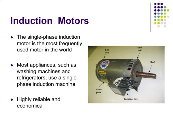
SCHRAGE MOTORS. Designed by Mr. H.K. Schrage - Swedish Engineer in 1911. It is a ROTOR fed, Shunt type, Brush shifting, 3 Ø Commutator Induction Motor which has built in arrangement both for speed control and p.f. control.

SCHRAGE MOTORS
E N D
Presentation Transcript
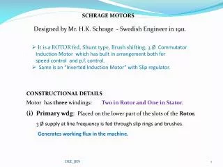
SCHRAGE MOTORS Designed by Mr. H.K. Schrage - Swedish Engineer in 1911. • It is a ROTOR fed, Shunt type, Brush shifting, 3 Ø Commutator • Induction Motor which has built in arrangement both for • speed control and p.f. control. • Same is an “Inverted Induction Motor” with Slip regulator. • CONSTRUCTIONAL DETAILS • Motor has three windings: Two in Rotor and One in Stator. • Primary wdg: Placed on the lower part of the slots of the Rotor. • 3 Ø supply at line frequency is fed through slip rings and brushes. • Generates working flux in the machine. DEE_JRN
Regulating Wdg: Placed on the upper part of the slots of the Rotor. • Connected to commutator segments in a manner similar • to that of d.c. machine. • Also known as tertiary wdg / auxiliary wdg / commutator wdg. • Secondary winding: Same is Phase wound & located on Stator. • Each Wdg connected to a pair of brushes arranged on the commutator. • Brushes mounted on brush rockers. • Designed to move in opposite directions, relative to the center line of its • stator phase. • Brushes A1 , B1 & C1 move together and are 1200 E apart. • Brushes A2 , B2 & C2 also move together and are 1200 E apart. DEE_JRN
WORKING OF SCHRAGE MOTOR • Primary energized with line frequency voltage. • Transformer action occurs between primary and regulating wdgs. • Induction motor action occurs between primary and secondary wdgs. • Commutator acting as a frequency converter converts line frequency • voltage of reg. wdg to slip frequency voltage and feeds the same to • secondary wdg on the stator. • Voltage across the brush pairs A1 - A2, B1 - B2 & C1 - C2 increases • as brushes are separated. • Magnitude of voltage injected into the secondary wdg depends on the angle • of separation ‘θ’ of the brushes A1 & A2, B1 & B2 , C1 & C2. • (‘θ’ – Brush separation angle) DEE_JRN
When primary is energized synchronously rotating field in clockwise • direction is set up in the rotor core. • Assume that the brushes are shortcircuited through commutator seg. • i.e. the secondary is short circuited. • Rotor still at rest, the rotating field cuts the stationary secondary wdg, • induces an e.m.f. The stator current produce its own field. • Stator field reacts with the rotor field thus a clockwise torque • produced in the stator. • Since the stator cannot rotate, as a reaction, it makes the rotor rotate • in the counter clockwise direction. DEE_JRN
Suppose that the rotor speed is Nr rpm. • Rotor flux is rotating with NS relative to primary & regulating wdg. • Rotor flux will rotate at slip speed (NS - Nr ) relative • to secondary wdg in stator / with reference to space. SPEED CONTROL Speeds above and below Synchronous speed can be obtained by changing the Brush position. i.e. changing “θ “ . Fig (a) – Brush pair on the same commutator segment. i.e. the secondary wdg short circuited. Injected voltage Ej = 0 and the m/c operates as an INVERTED Induction Motor. Nr < NS. DEE_JRN
Fig. (b) – Brushes parted in one direction - produces sub-synchronous speed. Injected voltage Ej , is obtained from the section of the regulating wdg between them. If the center line of this group of conductors is coincident with the centre line of the corresponding secondary phase, then E2 andEj are in phase opposition. Neglecting impedance drop, sE2 must be equal and opposite to Ej. “β” – angle between E2 andEj. β=1800& Nr < NS . Fig. (c) – Brushes parted in opposite direction - produces super-synchro. speed. Ej is reversed relative to E2. i.e. β=00 & sE2 must also be reversed. Same occurring only because ‘s’ becoming negative . i.e. The speed is thus above synchronous speed. Nr > NS . The commutator provides maximum voltage when the brushes are separated by One pole pitch. i.e. ‘θ’ = 1800 E. DEE_JRN
POWER FACTOR IMPROVEMENT • Same obtained changing the phase angle of the injected voltage • into the secondary winding. • In this case one set of brushes is advanced more rapidly • than the other set. • Now the two center lines do not coincide, • have an angle ‘ρ’ between them. (“ρ” – Brush shift angle) • Fig (d) : Brush set is moved against the direction of rotation of rotor. • In this case Speed decreases, the p.f. is also improved. • Fig (e) : Brush set is moved in the same direction of rotation of rotor. • In this case Speed increases, the p.f. is also improved. • Both p.f. and speed can be controlled by varying ‘θ’ & ‘ρ’. • ‘Ej Cos ρ’ and ‘Ej Sin ρ’ effect the speed and p.f. respectively. DEE_JRN
Speed Torque Characteristics Same reveals that the Schrage Motor is almost a constant speed motor. (SHUNT CHARACTERISTICS) • Applications • Can be applied to any individual drive requiring • Variable speed. Especially in • Hoisery knitting & Ring spinning m/cs. • Cranes & Hoists • Fans & Centrifugal Pumps • Printing Machinery • Conveyors, Packing machinery & Paper Mills DEE_JRN
ADVANTAGES • Good Speed Regulation. • High p.f. for high speed setting. • High efficiency at all speeds except NS. • DRAWBACKS • Operating voltage has to be limited to 700V because • the power is to be supplied through slip rings. • Low p.f. at low speed settings. • Poor commutation. • High Cost. DEE_JRN
Variation of no load speed with Brush Separation K= Turns Ratio= No: of Secondary turns / No: of tertiary turns DEE_JRN