Download
1 / 47
470 likes | 595 Views
Image Space Based Visualization of Unsteady Flow on Surfaces Robert Laramee Bruno Jobard Helwig Hauser Presenter: Bob Armstrong 24 January 2007. What's This About?. New Algorithm: ISBV

E N D
Image Space Based Visualization of Unsteady Flow on Surfaces Robert Laramee Bruno Jobard Helwig Hauser Presenter: Bob Armstrong 24 January 2007
What's This About? • New Algorithm: ISBV • Generates dense representations of arbitrary fluid flow on computational fluid dynamics (CFD) surfaces • Applied to unsteady flow on boundary surfaces of complex meshes from CFDs of more than 250K polygons, dynamic meshes, medical data • Seeing is believing
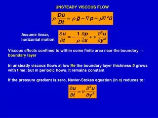
Visualization of flow on the surface of an intake manifold. The ideal intake manifold distributes flow evenly to the piston valves.
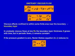
Visualization of flow at the complex surface of a cooling jacket – a composite of over 250,000 polygons
The Baldwin-Lomax model is a classical algebraic turbulence model which is suitable for high-speed flows with thin attached boundary-layers, typically present in aerospace and turbomachinery applications.
What's the Problem? • Traditional direct visualization of unsteady flow is computationally expensive • No real-time production • Animation/Simulation is expensive
Their Approach • Build off of Past Work • LEA • IBFV • Reduce complexity by generating 3D vector fields onto 2D image space
Past Work • Foundation for the ISBV Algorithm • Both produce dense representations of unsteady, 2D vector fields • LEA: • Lagrangian-Eulerian Advection • IBFV: • Image Based Flow Visualization
Lagrangian-Eulerian Advection • Produces animations with high spatio-temporal correlation • All data stored in 2D arrays • Each frame depicts instantaneous flow structure • Generates animations at interactive frame rates
Image Based Flow Visualization • Simulation of 2D fluid flow • Each frame of a flow animation is a blend between a warped version of the previous image and a number of background images. • Relies on graphics hardware
IBFV Method image k distort render blend k = k + 1 Note Distortion Phase: There is nothing to stop the image from being advected outside of the geometrical boundary.
Definition: CFD • Computational Fluid Dynamics • Branch of Fluid Mechanics • Relies on Numerical Methods & Algorithms
More CFD • How does one treat a continuous fluid in a discretized fashion on a computer? • Widely used: Discretize the spatial domain into small cells that form a grid or mesh • Apply suitable algorithm to solve the equations of motion. • www.cfd-online.com
Definition: Advection • Advection is transport of a conserved scalar quantity in a vector field. • A good example is the transport of pollutants or silt in a river: the motion of the water carries these impurities downstream.
Different Advections Velocity Vorticity Vorticity mapped to helicity More information here: http://www.vrvis.at/scivis/laramee/isa-streamsurface/
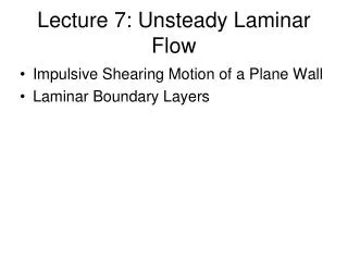
A hybrid stream surface-texture advection visualization showing tumble motion inside a gas engine cylinder. Texture is advected according to the velocity field and color is mapped to velocity magnitude.
The same stream surface geometry. Texture is advected according to the vorticity field and color is mapped to vorticity magnitude. The relationship to the velocity field can be explored in a novel fashion.
The same stream surface geometry. Texture is advected according to the vorticity field and color is mapped to helicity. Mapping color to helicity indicates candidate vortex core regions.
Traditional Visualization Methods • Maps one or more 2D textures to a 3D geometrical surface • Textured geometry rendered to an image space
ISBV Algorithm • Project surface geometry to image space • Apply texturing • Texture properties are advected in image space
ISBV Method (1) • Associate the 3D flow data with polygons at boundary surface • Project the surface and vector field onto the image plane • Identify geometric discontinuities • Advect texture properties according to the vector field in image space
ISBV Method (2) • Inject and blend noise • Apply additional blending along the geometric discontinuities previously identified • Overlay all optional visualization cues such as showing a semi-transparent representation of the surface with shading
Flow Diagram Dynamic Case k = k+1 Vector Field Projection Edge Detection Compute Advection Mesh Image Advection Static Case k = k+1 Noise Blending Edge Blending Image Overlay Application k = time as a frame #
Vector Edge Projection • Project vector field to the image plane • Velocity vectors stored at the polygon vertices • Encode velocity vectors as color values at the mesh vertices
Color & Velocity Component • Color assignment done as a scaling operation • Each color component assigned velocity
Why Use Velocity Image Fields? • Advection computation, noise blending simpler in image space • Vector field and polygon mesh decoupled • Hardware-accelerated occlusion culling • Supported on graphics hardware
Velocity Vectors • Decoded vectors used to compute advection mesh, then projected upon the image plane
Timing of Projection of Vectors • Project vectors to image plane after velocity image construction • Don't have to project all vectors • Use original 3D vectors for the velocity mask
Edge Detection • Edge detection solves the problem of artificial flow continuity because of artifacts from 3D to 2D image space projection • Selectively detects only edges affecting flow texture properties
Edge Blending • During this phase of the algorithm • Introduce discontinuities in the texture aligned with discontinuities from the surface • Essentially, ensure that edges are accounted for visually
Geometric Edge Detection Disabled Enabled
Compute Advection Mesh • Distort regular, rectilinear mesh according to velocity vectors stored at mesh grid intersections p is a path line, kis a frame Above ensures that distortion does not extend beyond geometric boundaries.
Image Advection & Texture Clipping Coarse Resolution Advection Mesh, With Artifacts Texture Clipping applied
Noise Blending • Use IBVF method for noise injection and blending
Blending Sample Blended Image Sample Noise Image
No Edge Blending With Edge Blending
Image Overlay Application • Optional step • Overlay enhances visualization with colorization, shading, etc. Overlay Applied Composite of All
Vector Projection • The projection of the vectors to the image plane is done after velocity image construction for 2 reasons: • not all of the vectors have to be projected, thus saving computation time • can use the original 3D vectors for the velocity mask
Performance Discussed • Authors looking for speedup; specifically, increased frame rates • up to 20 fps • Performance tied to image resolution & polygon count (unsteady state flow) • Don't have any good comparative figures
79K polygons dynamic geometry dynamic topology time-lapsed pics