Download
1 / 22
400 likes | 2.25k Views
Overview of Unsteady Flow Modeling With HEC-RAS. Gary W. Brunner, P.E. Introduction. Overview New Geometric Features for HEC-RAS Geometric pre-processor Boundary and initial conditions Unsteady flow simulation manager Post-processor Additional graphics/tables to view results. Overview.

E N D
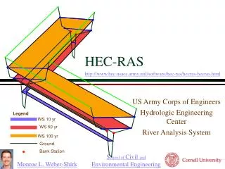
Overview of Unsteady Flow Modeling With HEC-RAS Gary W. Brunner, P.E.
Introduction • Overview • New Geometric Features for HEC-RAS • Geometric pre-processor • Boundary and initial conditions • Unsteady flow simulation manager • Post-processor • Additional graphics/tables to view results
Overview • Common geometry and hydraulic computations for steady & unsteady flow • Using the UNET equation solver (Dr. Robert Barkau) • Can handle simple dendritic streams to complex networks • Able to handle a wide variety of hydraulic structures • Extremely fast matrix solver
New Geometric Features for RAS • Existing Geometric Features all work for unsteady flow (XS, bridges, Culverts, inline weirs/spillways) • Lateral Weirs/Spillways • Storage Areas • Storage Area Connections (weirs, gated spillways, and culverts) • Pump Stations
Pre-processing Geometry • For unsteady flow, geometry is pre-processed into tables and rating curves • Cross sections are processed into tables of area, conveyance, and storage • Bridges and culverts are processed into a family of rating curves for each structure • Weirs and gated structures are calculated on the fly during unsteady flow calculations • Pre-processor results can be viewed in graphs and tables
Cross Section Properties Plot Property Table RS = 138154.4 700 Legend Conv. Channel 690 Conv. Valley Conv. Total 680 Storage Elevation (ft) 670 660 650 0 1000 2000 3000 4000 5000 6000 7000 Conveyance/1000 (cfs) Storage (cu ft)
Boundary conditions must be established at all ends of the river system: Flow hydrograph Stage hydrograph Flow and stage hydrograph Rating curve Normal depth Boundary and Initial Conditions
Interior boundary conditions can also be defined within the river system: Lateral inflow to a node Uniform lateral inflow across a reach Ground water interflow Time series of gate openings Elevation controlled gate Navigation Dams Observed internal stage and/or flow hydrograph Boundary and Initial Conditions
Boundary and Initial Conditions • Initial conditions must be established for the entire system: • Specify flows and perform a steady flow backwater analysis • Read in flow and stage at every node from a previous run, “hot start” file
Unsteady Flow Simulation Simulation Manager 1. Define a Plan 2. Select which programs to run 3. Enter a starting and ending date and time 4. Set the computation settings 5. Press the Compute button
HEC-RAS Computation Window Geometric Pre-Processor Unsteady Flow Simulation Post Processor Computational Messages
Simulation Options • Stage and Flow Output Locations • Flow Distribution Locations • Flow - Roughness Change Factors • Seasonal Roughness Factors • Friction Slope Method • Output Options: • Write out Restart File • Detailed Log level output
Simulation Options- Continued • Encroachments - Method 1 Only • Dam Breaching • Levee Breaching • Mixed Flow Regime • Checking Data Before Computations • Viewing Computation Log File
Post-processing Results • Used to compute detailed hydraulic information for a set of user-specified time lines and an overall maximum water surface profile. • Computed stages and flows are passed to the steady flow program for the computation of detailed hydraulic results
Viewing Unsteady Flow Results • All of the output that was available for steady flow computations is available for unsteady flow (cross sections, profile, and 3D plots and tables). • Stage and flow hydrographs • Time series tables • Animation of cross section, profile and 3-dimensional graphic