Download
1 / 14
140 likes | 158 Views
This document provides an overview of the Argonne Laser Test Stand, including measurements and challenges, as well as an overview of the Fermilab Test Beam Facility. It discusses the equipment used, such as the Hamamatsu PLP-10 Laser, and outlines the next steps for fully characterizing the sensors and readouts. Additionally, it provides information on the Fermilab Test Beam Program, including the beam extraction process and available user stations.

E N D
Argonne Laser Test Stand andFermilab Test Beam FacilityKaren Byrum8 March, 2007 • Status of Argonne Laser Teststand (Joint ANL – UC program) • Some first measurements (Argonne) • Overview of Fermilab TestBeam Facility (E.Ramberg) • FNAL Facility Capabilities at TestBeam
Argonne Laser Test-stand • Challenges with Testing psec timing • Must Build Entire Sensor/Readout Chain to Fully Characterize Performance • Need Specialized Equipment, Ultimately a Test Beam • Two Step Plan • Use ANL LED Test stands and setup a new laser laboratory • Fully Characterize MCPs which we are specifying and Burle/Photonis is designing. • A way to systematically measure sensor + readout in controlled environment • Ultimately, take the sensor + readout to the FNAL testbeam and test in particle beam.
Hamamatsu PLP-10 Laser • Controller with a laser diode head • 11 heads available – frequencies from 375 nm to 1550 nm (we purchased 405 nm & 635 nm) • 405 nm head – pulse width max 100 ps – typ. 80 • Pulse to pulse jitter < 10psec http://sales.hamamatsu.com/en/products/system-division/ultra-fast/picosecond-light-sources/plp-10.php?&group=1
Laser Lab – Current Components • Camac CC-USB processor/ connected to laptop running linux • Phillips 7186 25psec/bin TDC • Ortec 9306 Preamp • Ortec 9307 CFD • Ortec 9308 1-channel 1psec/bin TDC (on loan to Jerry) • Hamamatsu PLP-10 Laser with 2 heads • Optical Table • Copper shielded Dark Box
Setting Up laser MCP Camden Ertley R8900 Hamamatsu MaPMT
Calibration Beam is broad ~2-3cm Skewing Parameter Speed of Light
First Look at Mark-0 Mark0 • Mark-0 is first of 4 devices (we have ordered) • Mark-0 Burle 85011 2” x 2” • 64 outputs (8x8 array) ~38ps
What’s next • Fully characterize and understand laser beam to MCP performance. (ie laser power, beam size on MCP…) • Add more instrumentation (enough to readout 2 MCPs) • Instrument laser stand with 2 MCPs on xy stagers. • Add filter wheel, etc.
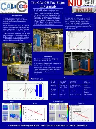
THE FERMILAB TEST BEAM PROGRAM Linac Booster Anti-proton accumulator Main Injector SwitchYard (and to Meson area) • Extraction of beam from Main Injector: • From 1 to 6 batches in the Main Injector • Each batch from 0.2 to 1.6 sec in length • A fraction of the beam is resonantly extracted in a slow spill for each MI rotation • 3 batches equals ~1E12 protons • The slow spill to the SwitchYard is currently one 4 second spill every minute, for 12 hours a day • The slow spill Switchyard beam competes in time with anti-proton production and MINOS targeting
MTest Profiles 120 GeV proton mode Tune (GeV) Rate in MT6/spill* e- fraction 120 800,000 0 66 90,000 0 33 40,000 0.7% 16 14,000 10.0% 8 5,000 30.0% 4 500 60.0% * (Rates are normalized to 2.4E12 protons in Main Injector) Measured rates in the MTBF beamline
Web page for MTBF: http://www-ppd.fnal.gov/MTBF-w or Fermilab-at-Work MTBF Test beam coordinator: Erik Ramberg - ramberg@fnal.gov - 630-840-5731 Scale: ~6 m 6 user stations. An experiment can take up more than one station. 2 climate stabilized huts with air conditioning. 2 separate control rooms. 60 signal cables/20 HV cables to each area Outside gas shed + inside gas delivery system brings 2 generic gas lines, 1 nitrogen line and 2 exhaust lines to each of the user areas Lockable work area with 3 offices for small scale staging or repairs, plus 2 open work areas.
Setup of Meson Test Beam Facility tracking DAQ • Facility Capabilities include: • TOF counters • Cerenkov Detectors • Tracking system Section 2 Section 1 MWPC MWPC MWPC MWPC TOF TOF CKOV crate 3 crate 4 crate 5 crate 7 DAQ computer (mtbf.fnal.gov) CAMAC crate 1 Electronics room Control room MS4 Power Supply Service Area
Improvements to the Test Beam • About 6 months ago, Fermilab initiated a very significant investment in the Meson Test Beam Facility. • As a consequence of this investment, both the beamline and user facilities were improved considerably over the last few years of running. • The beamline improvements include: • An intermediate moveable target which will increase low energy pion flux • Low current power supplies and Hall probes to stabilize low energy tuning • Minimization of material in the beamline to reduce scattering and conversion • Ability to bring primary proton beam flux on an electron target • Quadrupole triplets to enhance tuning. • The user facility improvements include: • Thorough cable installation • New control/conference room • 4th tracking station • New TOF system and differential Cerenkov detector • Motion tables and video system • Laser alignment • The beamline is being commissioned now and has achieved a range of 2 to 120 GeV beam.