TEAM 2
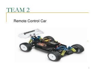
This project features a remote control car with a two-way antenna for data transmission, manual and automatic light control, display for speed and battery life. With a team of experienced engineers, we provide comprehensive design, verification, and documentation services.

TEAM 2
E N D
Presentation Transcript
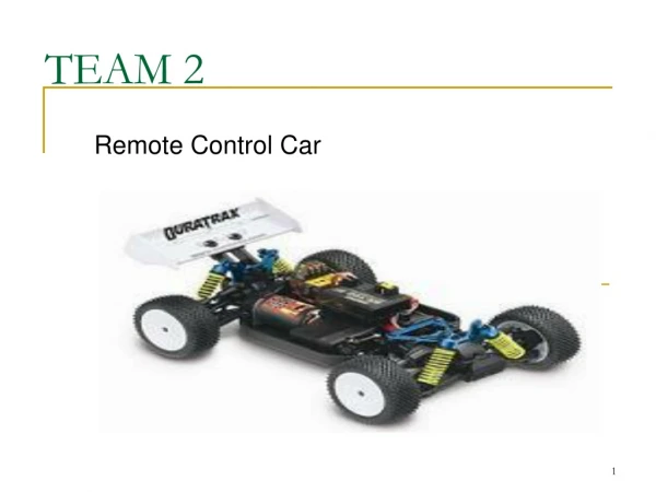
TEAM 2 Remote Control Car
Team #2: Total Resources • LPI-Sean Murphy (BSEE) • LSD-Russ Diamond (BSEE) • LPM-Adam Wozniak (BSEE) • LRM-Brad LaCount (BSEE) • LMM-Barry Gentz (BSEE)
Project Features • The remote control car has a two-way antenna that can transmit to and receive data from the car. • Control of the car will come from the controller. • The car can turn its lights on and off manually, and automatically if it gets dark enough. • The display will tell us the speed and direction of the car, and the battery life remaining.
As of 3rd Week Manhours-500 Material $500 ~2% for design ~86% for detailed design ~2% for verification ~10% for documentation End of Project Manhours-1702 Material $1031 These values may be off due to overlapping of projects. Estimation Slide
Competitor’s Slide RequirementUnits to Specify • Competitors • Market Size • Average List Price • Market Geography • Market Demography • Intended Application • Material Cost • Manufacturing Cost • Annual Volume • User Manual • Traxxus, Tra5510 • $600 million, website • $200 • World-Wide • 6 yr. old to adult, boys • Home, toy • $80 / unit • $20 / unit • 6 million / yr • Included
System - Std Reqs: Mfg & Life Cycle RequirementUnits to Specify • Max Parts Count • Max Unique Parts Count • Parts/Mat $ Allocation • Asm/Test $ Allocation • Product Life, Reliability • Full Warranty Period • Service Strategy • 200 Total Parts • 100 Unique Parts • $80 (Parts+Mfg=Product Cost) • $20 (Parts+Mfg=Product Cost) • 3 yrs • 6 months • Repair
System - Std Reqs: Production RequirementUnits to Specify • Max Volume • Shipping Container Size • Max Mass • Max # of PC Bds • Max PCB Circuit Area • Max Shock • 12,000 cm3 • 18,000 cm3 • 2 Kilograms • 5 • 500 cm2 Total • 50 G force
System - Std Reqs: Power Interfaces RequirementUnits to Specify • Min Oper Voltage Range • Max Power Consumption • Max Energy Consumption • Car Battery Chemistry • Car Battery Capacity • Controller Battery Pack • Controller Display Segments • Controller Accuracy • Modes of Operation • 5-9.0 V and 5-15.0 V • 18.0 Watts Total • 6000 mAH Total • Nimh • 6000 mA-Hrs • i.e. AA 1.5V • 10 bars • 15% battery life • On/Off
System - Std Reqs: Enviroment RequirementUnits to Specify • Min Oper Temp Range • Min Oper Humidity Range • Min Oper Altitude • Min Storage Temp Range • Min Storage Humidity Range • Min Storage Altitude • Max Storage Duration • 10-45 Co • 10-90% non-condensing • 0-3000 Meters • 0-80Co • 10-90% non-condensing • -200-3500 Meters • 1 year
System – Perf Reqs: Display • LCD Display: • Display size: • Max. Display Distance: • Viewing Environment: • Display Char Matrix: • Display Size: • Display Illumination: • Mono Color • 150mm x 70mm • 1 meter • Any • 20 Total Char/Row, 4 Total Rows • 20cm x 10cm • LED
System – Perf Reqs RequirementDefinition • Lights • Power Saving Modes • Speed Accuracy • Microprocessor Updates • Speed Range • Controller Accuracy • Response Time • Input/Output • Max. Delay • Min EM Transmission Distance • ON/OFF/AUTO • None • ± 3 mph • 200 ms • 0-40 mph • 8 Directional Units • 200 ms • 0-5V logic levels • .005 s • 300 ft
System – Perf Reqs: Safety Standards • We will be using the standards UL 2202 1.5, UL2111 1.5, UL 1977, Cispr 61000-6-3, EMC 61000-4-2, EMC 61000-4-4, and EMC 61000-4-5 in order to make sure that our product is safe. • These standards insure that there is no risk to the user from the product and vice versa. • The EMC standards protect our product from ESD and power surges.
Team #2: Project 1Block Assignment Digital RF Trans / Rec Sean [4] RF Trans / Rec Sean [4] Digital Digital Digital Power Supply Brad [2] Ctrlr Processor Brad [3] Car Processor Russ [6] On Car Sensing Adam [8] Digital Analog Analog Electromechanical Control Russ[7] Digital Signal Input & Display Barry [1] Power Source Sean [5] PCB 1, power supply will be connected to all blocks PCB 2, power supply will be connected to all blocks
Signal Input Designed by: Barry Gentz
Block 1: Signal Input • Theory Of Operation: Signal input takes in the users desires for the speed, direction and light position and implements them to the car’s motion, direction or state.
Block 1 - Std Reqs: Environmental RequirementUnits to Specify • Min Oper Temp Range 10-45 Co • Min Oper Humidity Range 10-90% non-condensing • Min Oper Alt or Press Range 0-3000 Meters • Min Storage Temp Range 0-80Co • Min Storage Humidity Range 10-90% non-condensing • Min Storage Alt Range 0-3000 Meters
Block 1 - Std Reqs: Safety RequirementUnits to Specify • Max Storage Duration 1 year • Safety Standards 61000-4-2 61000-4-4
Block 1 - Std Reqs: Power Interfaces RequirementUnits to Specify • Source Connection List Permanent • Operating Voltage Range 4.9-5.1 V • Max Power Consumption 3.0 Watts • Max Energy Consumption 100 mAH • Max Potential 0V
Block 1 - Std Reqs: Mechanical RequirementUnits to Specify • Max # of PC Bds 1 • Max PCB Circuit Area 100 cm2 Total • Max Volume 200 cm3 Total • Max Weight .5 lbs • Max Shock 50 G force
Block 1 - Std Reqs: Manufacturing Costs RequirementUnits to Specify • Parts/Mat $ Allocation $25 • Asm/Test $ Allocation $50
Block 1 - Std Reqs: Parts Count & Reliability RequirementUnits to Specify • Max Parts Count 30 Total Parts • Max Unique Parts Count 10 Unique Parts • Product Life, Reliability 3 yrs • Full Warranty Period 6 months • Product Disposition Dispose • Service Strategy Dispose or Repair
Block 1 – Perf Reqs: I/O Requirements-Modes RequirementDefinition • Max Error Voltage .25V • Operational Modes - Fast/Slow/Stopped - Left/Right/Straight - On/Off/Auto
Block 1 – Perf Reqs: Signal Interface Req’s Response time < 250ms Digital Signals • Noise must be -40dB at 10 Hz • Power input = Vref [DC (AA batteries)] Analog Signals
Block 1 – Perf Reqs: User Interfaces RequirementType • Speed Control Vertical Pot wheel • Direction Control Vertical Pot trigger • Light Switch 3 position switch
Team #2: Project 1Block Assignment Digital RF Trans / Rec Sean [4] RF Trans / Rec Sean [4] Digital Digital Digital Power Supply Brad [2] Ctrlr Processor Brad [3] Car Processor Russ [6] On Car Sensing Adam [8] Digital Analog Analog Electromechanical Control Russ[7] Digital Signal Input & Display Barry [1] Power Source Sean [5] PCB 1, power supply will be connected to all blocks PCB 2, power supply will be connected to all blocks
Block 1- Detailed Design: Sub-Block Design Analysis Plan Steering1 5K Pot ESD LP Filter Speed1 Processor 5K Pot ESD LP Filter Lights Switch ESD De-Bounce S.T. Digital Signal Analog Signal Power Signal Power
Block 1- Detailed Design: Signal Type Digital Analog
Block 1- Detailed Design: Filter Calculations • Transfer Function: • 2nd order filter is need to increase the steepness of curve.
Block 1- Detailed Design: Filter Calculations • Transfer Function: • Since R1=R2=130k and C1=C2=1.5uF • (1/R2C2)/[s2 + s(3/RC) + (1/R2C2)] • fc = .816 Hz
Block 1- Detailed Design: Light Switch • Switch logic • Debounce Calculations: • TDB = RC = 20000*10^(-6) = 20ms
Block 1- Detailed Design: Schmitt Trigger 74HS14 • Vutp = 2.85V • Vltp = 1.85V • VHYST max = 1.5V • VHYST min = 1.0V
Block 1- Detailed Design: DFM-Capacitor Specs • Capacitor’s • Rated to 10V • 10% tolerance in Capacitance rating • Axial packaging
Block 1- Detailed Design: DFM-Packaging Selections • The switch is mounted on the PCB. • The pot’s are aux mounted on the controller. • All other parts are SMT.
Block 1- Detailed Design: Safety Features • Provided Shock Protection ESD > 15 kV • Over Voltage Protection Diode > 20 kVR • Safety Standards 61000-4-2 • 61000-4-4
Block 1- Detailed Design: Reference Voltage Bandgap Vref
Block 1- Detailed Design: DFM-DC Drive Analysis Table • Vxx in Volts, Ixx in mA • Source Currents Listed as Negative • Std = Standard
Block 1 – Mfg Design: Flow Chart/Assembly Order/Receive Parts Initial Assembly Testing Final Assembly Final Testing Ship to Customers/Stores
Block 1 – Mfg Design: Testing • Functional tests are needed after initial assembly which include : • Checking outputs of block to look for desired voltage levels. • Make sure all Functions work before final assembly
Block 1 – Reliability Analysis: Unreliability • Worst parts: (According to Calculated FITS) • Resistors at 72.8 • Potentiometers at 50 • OP-Amp’s at 38
Block 1 – Obsolescence Analysis: Summary Worst part
Block 1 – Legal/Societal/Ethical Aspects: Summary • Entire Block is ROHS compliant. • Block includes no Hazardous materials. • Due to automated placement of parts, block can be assembled anywhere. • Most common failure i.e. pot breaking, will result if abused.
Controller Power Supply Designed by: Brad LaCount
Controller Power SupplyDescription • Converts a 9V DC input into a regulated 5V DC output. • Distribute the output to the display, CPU, Rec/Tran circuit, and input signals.