Download
1 / 38
380 likes | 395 Views
R&D Opportunities in Linear Collider Tracking Dan Peterson Cornell University LCCOM 19-April-2002. Baseline Detectors Momentum resolution and implications Jet track density and implications Resolution and segmentation in various technology, R&D issues TPCs

E N D
R&D Opportunities in Linear Collider Tracking Dan PetersonCornell UniversityLCCOM 19-April-2002 Baseline Detectors Momentum resolution and implications Jet track density and implications Resolution and segmentation in various technology, R&D issues TPCs drift chambers / jet chambers (baseline in Asia, not considered in N.A. or Europe) new technology gas amplification TPCs all silicon trackers Simulation work
Physics Goals, Implications clean Higgs signal from di-lepton recoil mass end-point mass spectra in SUSY cascades d(1/Pt) ~ few 10–5 /GeV jet energies in W+W- final states (energy flow analysis ) exceptional pattern recognition, 2-track separation Primary and secondary vertex reconstruction radially continuous tracking
The large detector baseline design, LD Goal: optimized tracking precision with large tracking volume Magnetic field: 3 Tesla North American LD baseline design Stolen from K. Riles, Chicago Linear Collider Workshop, 7-Jan-2002
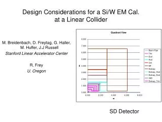
The “silicon detector” baseline design, SD Energy flow calorimetry -> Expensive calorimeter -> Small calorimeter -> Limit tracking system Outer radius to 125 cm Compensate for a smaller measurement length with improved spatial resolution (although fewer points) and higher magnetic field Magnetic field: 5 Tesla North American SD baseline design Stolen from K. Riles, Chicago Linear Collider Workshop, 7-Jan-2002
TESLA tracking system Magnetic field: 4 Tesla cos(q)=.995 Stolen from TESLA TDR (differences, wrt North American LD) 1.7 m radius ( vs 2 m) , 4 Tesla field (vs 3 Tesla in N.American LD) SIT is an intermediate tracking device, 2 layers FCH is a straw tube device, 6 double layers, resolves TESLA bunch (340 ns)
Momentum Resolution & Spatial Resolution d(1/R)=s/L2(720/(N+4)).5 “L” is the measured track length “s” is the measurement error PHYSICS GOAL: d(1/pt)=3 x 10 –5 / GeV Pinning the fit at the IP improves resolution by ~ 2/3 R=Pt / (.3 GeV/Tesla B ) use measurement length: L = 2 meters (LD) use N = 100 d(1/Pt)=s/L2(720/(N+4)).5 (.3 GeV/Tesla B ) s/B = 20 micron/Tesla, or s = 100 micron resolution, with B = 5 Tesla
(relaxed ) PHYSICS GOAL: d(1/pt)=4 x 10 –5 / GeV Momentum Resolution d(1/pt)= goal is difficult with tracking chamber and vertex detector alone. Try an intermediate silicon device, R=.45 meter, srf = 10mm, N=2 (relaxed) magnetic field: 3 Tesla Tracker: 2m OR , 0.5m IR Vertex detector: 5 layer, 10 mm tracker 100 mm ----d(1/p)= 5.0 x 10⁻⁵ /GeV with VD only, no int. tracker(consistent with previous slide) tracker 100 mm ----d(1/p)= 3.5 x 10⁻⁵ /GeV with VD and int. tracker tracker 150 mm ---- d(1/p)= 4.2 x 10⁻⁵ /GeV with VD and int. tracker * Results from Dan’s fast MC tracker 150 mm ----d(1/p)= 6.0 x 10⁻⁵ /GeV with VD and int. tracker(misaligned by 25 mm, 1 mil )
Spatial Resolution Spatial resolution requirement is aggressive, 100 mm in 5 Tesla field. (This result is for a large chamber (r=2 m) in combination with a perfect vertex detector which constrains the fit at the vertex. ) Momentum resolution goal can be met with 150 mm in 3 Tesla field. (This result is for LD, a large chamber (r=2 m) with a vertex detector and intermediate detector , both s = 10 mm. ) However, the resolution is sensitive to misalignments . Large TPCs do not meet either spatial resolution goal. For example, Aleph: s = 180 mm, STAR : s = 500 mm . This resolution is partially related to the pad spacing, which comes with the induction readout. Aleph resolution is 3% of the pad spacing ( 6.2 mm ). STAR resolution is 8-17% of the pad spacing (6.2 or 2.9 mm). Drift chambers can provide 100 mm spatial resolution. Let’s see what else is a problem ….
Track Density This “typical” jet has 19 tracks projected onto an azimuthal angle of 30o. This is a track density of 88 tracks/ster(for conical jets) . I will use 100 tracks/ster as pattern recognition goal. JAS 2D LCD Event Display Stolen from N. Graf, Chicago Linear Collider Workshop, 7- Jan-2002
Compare with the STAR TPC Is 100 tracks/ster large? Yes, that would be 1250 tracks in the event. STAR observes 1000 to 2000 tracks per event. Is this demonstration that a TPC can operate with this track density? No, perfect efficiency is not a goal at STAR; look at those panel cracks! Spatial resolution requirement is relaxed; s = 500 mm. Must do better! multi-track event in STAR TPC at RHIC Stolen from J. Thomas, Vienna Conference on Instrumentation , 22-Feb-2001
TPC Segmentation and Occupancy (induction read-out) Z segmentation is limited by the signal time width, but usually by the Z travel of the track. Z segmentation is typically equal to height of the pad, 10mm ? 20 mm ? r-f segmentation is limited by the induction read-out. (Gas amplification is due to an avalanche on a wire. Induction signals on pads are read out. ) STAR signal width, 2-track separation: 25 mm. Occupancy: at r=50 cm, with r-f segm.= 2.5 cm, Z segm. = 1 cm, segmentation is 1/1000 ster; occupancy (in jet) is 10% , there will be overlapping tracks
Track Overlap in a TPC Overlapping tracks are complicated in a TPC. Pulse height signals on pads can not be resolved beyond the intrinsic segmentation of the device. Merged signals have ambiguous position measurement; >> s. Two tracks in STAR TPC Stolen from J. Thomas, Vienna Conference on Instrumentation , 22-Feb-2001
R&D projects, TPC (induction) tracker The (induction) TPC is the baseline, or backup, for advanced readout methods (described later). Spatial resolution optimization, goal of 150 mm in a large induction TPC. Ion feedback suppression; gating grids ( long gate time at TESLA ) Gas studies: aging, velocity (clearing time), quenching, neutron absorption Alignment: internal alignment and drift path in an inhomogeneous B field extrapolation to an intermediate tracker: hardware & tracking. (with poorer resolution, system is more dependent on intermediate tracker) (simulation) Optimize pattern recognition in an environment of significant track overlap.
Drift Chambers Drift chambers are largely not considered by North America and Europe groups. Disadvantages: “poor segmentation” (discussion follows) wire sag and electro-mechanical instability wire tension load on endplate, endplate thickness Lorentz angle in a high magnetic field current limitation Drift Chamber (Jet) is the baseline design in Asia. Advantages: spatial resolution: 88 mm for 80% of hits (CLEO) 2-track separation better than segmentation (will discuss for 14 mm square cell design )
Track Overlap in a square celldrift chamber In drift chambers, there is no Z segmentation. jet track density: 19 tracks/30o 36 tracks/radian 0.7 tracks/cm at R=50 cm Within the orange circle: 3 tracks within 2 cell widths (note separation:yellow circle). Observed density: 1.1 tracks/cm 55 tracks/radian at R=50 cm Tracks are resolved up to this density if sufficient separation exists elsewhere on the track. CLEO MC event
Track Overlap in a square celldrift chamber, resolved Multi-tracks can be resolved beyond the device intrinsic segmentation because the time measurement is valid for one of the tracks. (some of the hits, all the time) Method involves extrapolating in from isolated hit region. Track separation is better than intrinsic segmentation. Applies to Jet Chamber. Display of hit residuals (horizontal) of hits on a track (in white on prev. slide) .
Jet Chambers Jet chamber: 4 mm segmentation (a 2 mm track separation, measured in a single layer, is doubled by the ambiguity) ( while the square cell example had 14 mm segmentation ) Track separation is better than the 4 mm segmentation as shown for the case of square cell chamber. Disadvantage: discontinuous tracking due to complicated field cage shaping Expect a track density limit of 1 track/4mm at R=50 cm 125 tracks/radian CDF event CDF Jet Chamber event Stolen from Y-K Kim, 2001 Lepton Photon Symposium , 23-July-2001
R&D , Jet Chamber, ongoing/planned (KEK) (I will discuss these R&D results.) Wire sag and electro-mechanical instability 2-track separation Lorentz angle ( and drift velocity ) Spatial resolution (“understood” at CLEO) Stable operation of stereo cells Aluminum wire creep (I will not discuss results/plans in) Gas gain saturation (affects dE/dx, 2-track separation) Neutron backgrounds Optimization of gas mixture (what should be studied) Careful study to reconstruction vs track density with full MC.
Jet Chamber: wire sag, electro-mechanical instability 5 sense wires/cell, 7 cm height 5 cm drift Note: triple field wire will reduce instability Wire positions measured with CCD cameras. Sense wire sag: ~ 300 mm , field 600 mm Motion with voltage on minimal, no instability observed Stolen from JLC website, N. Khalatyan, Tsingua
Jet Chamber2-track separation Small jet cell chamber in test beam e+e- pairs from conversions FADC signals analyzed for separation Observe 2 mm separation Stolen from JLC website, K. Fujii, FermiLab 2000
Jet Chamber:Lorentz Angle,Spatial Resolution CO2 – Isobutane (90:10) velocity: 7.8 mm/ns, (faster near wire) live time : 7 ms Lorentz angle: 10o at 2 Tesla, 19o at 4 Tesla Resolution 100 – 150 mm Stolen from JLC website, N. Khalatyan, Tsingua
TPC with GEM or MicroMEGAS read-out Advantages: electron collection, 100 mm spacing Signal width is significantly reduced, improved segmentation E x B effect (in radial part of electric field) which limits resolution in an induction readout is reduced with signal width Problems: New technology Signal width may be too small. Must extract optimum resolution with finite # of channels. Gem TPC read-out Stolen from TESLA TDR Signal size in GEM and induction read-out Stolen from M. Ronan, Vienna Conf. on Instrumentation , 22-Feb-2001
R & D, TPC , GEM/MicroMEGAS read-out Pad size: narrow electron cloud ~ 1mm requires 1mm pads to provide charge sharing, O(106) pads wider pads (5mm?) will have poor resolution: w/(12)1/2 Pad shape: methods of spreading signal to limit channel count and improve resolution chevrons? ganging? Induction? Beware, efforts to spread signal may compromise 2-track separation. Aging: GEMs can fail at high gain, relatively new technology, dependence on gas choice Gas: diffusion, velocity Active R&D Achen, Carleton/Montreal, DESY/Hamburg, Karlsruhe, Krakow, LBNL, MIT-Munich, MPI, NUKHEF, Novosibirsk, Orsay/Saclay, Purdue
GEM point resolution, Carleton X-ray incident on indicated point. (not a TPC) Charge shared signal is observed on 3 pads (2.5 mm hex). Direct charge collection signal has about 1 ms width, 10 MHz Charge sharing contours (lower right) indicate that signal width is 1 mm. Spatial resolution is < 100 mm, but only 1mm from boundaries. X-ray signal spatial resolution Stolen from D. Karlen , Chicago Linear Collider Workshop, 7-Jan-2002
GEM point resolution (induction), Carleton Also measured induction signals on 4 neighboring pads. (same event) Spatial resolution is < 100 mm and not dependent on 1 mm pad size. Signal width (threshold-threshold) 0.1 ms, requires 50-100 MHz However, induction is inconsistent with 2-track separation; could be used in isolated sections to improve resolution.
TPC with GEM Read-out,Carleton Resolution with P10 gas 220 mm , z<10 mm 560 mm , 70<z<150 mm Explanation: large diffusion contribution (no magnetic field) Extrapolates to 200 mm at z=0 Questions: ion statistics ? (5 mm pad height) anomalous electron cloud size ? Cosmic signal spatial resolution Stolen from D. Karlen , Chicago Linear Collider Workshop, 7-Jan-2002
Micro Pattern Detector Aging (Radiation Hardness), Purdue Example triple GEM with PCB readout Gas Ar/CO2 70/30 (99.99%) GEM1= 400 V GEM2= 390 V GEM3 =380 V PCB as e- collector Cr X-rays (5.4 KeV) @ 6 x 10⁴ Hz/mm2 for 750hrs Gas gain 6,000 Detector performance small (~15% gain loss) after ~ 8 years @LHC 10 cm from IP. No visual sign of aging. Best result obtained with a GEM. Similar result obtained with A MicroMEGAS + GEM Stolen from I. Shipsey, NIM A 478 (2002) 263
R & D, TPC , GEM/MicroMEGAS read-out, cont. Tests in high magnetic field: reduce transverse diffusion, surprises Electronics: sampling rate, Aleph:11 MHz, 100 Mhz required for faster gas or induction from neighboring pads Typical live time may be 50 ms, store 1 ms exposure at TESLA . Amplification: signal size, break-down limit, pad height, gas Mechanical: mounting gas amplifiers, minimizing inactive regions high speed sampling may require cooling (and, as in induction read-out TPC) Ion feed-back: multi-GEMs or MicroMEGAS (appears better) and/or gating grid Gas: quenching with hydrocarbons vs neutron cross section Alignment methods: internal, external, consistant with improved resolution (and, in an inhomogeneous magnetic field)
Provides: improved segmentation • d(1/Pt) in a small package Diasadvatages: • pattern recognition issues • material issues (low momentum) • limited dE/dx • 2 technologies being pursued by • North American groups • Silicon m-strip • Silicon Drift All Silicon Tracking d(1/Pt)= s/L2(720/(N+4)).5 (.3 GeV/Tesla B ) With L=1.25 m, B=5 Tesla, s = 10 mm, N=6 d(1/p)= 3.6 x 10⁻⁵ /GeV Stolen from B Schumm, SILC phone/web meeting, 4-Apr-2002
R & D , all silicon tracking Organizational meeting: April 4, Bruce Schumm, UCSC Silicon m-strip: R&D, UC Santa Cruz reduce material, detectors must be very thin, 200 mm + no support (CLEO 300 mm plus support) to compete with budget of TPC ( 1.3% Xo in inner support) long shaping time, allows ultra low noise for thin detectors, 10 ms (CLEO <3 ms ) minimal support material, possibly tensioned power cycling, reduce heat load, can this be done without adding noise? resolution, 50 mm pitch with centroid finding for required 7 mm Silicon Drift : R&D, Wayne State (next page)
Silicon Drift Detector Electron drift in silicon, r-f from pad, z from drift time Maximum drift: 5 ms Mature technology, STAR vertex detector LC Central tracker Five layers Goals: Radiation length / layer = 0.5 % s (r-f) = 7 mm, s (z) = 10 mm Wafer size: 10 by 10 cm Wafers: 6000 (incl. spares) Channels: 4,404,480 (260 mm pitch) Stolen from V. L. Rykov , Chicago Linear Collider Workshop, 7-Jan-2002
R & D , silicon drift detector Ongoing/planned at Wayne State Improve radiation length, STAR is 1.4 % per layer Reduce wafer thickness from 300 to 150mm Move FEE to edges or change from hybrid to SVX Air cooling vs. water cooling More extensive radiation damage studies. Detectors/FEE can withstand around 100 krad (g,n) Improve position resolution to 5mm Decrease anode pitch from 250 to 100mm. Stiffen resistor chain and drift faster. PASA is BIPOLAR (intrinsically rad. hard.) SCA can be produced in rad. hard process .
Intermediate tracker,Forward Disks Motivation: improve momentum resolution extend efficiency to cos(q)=.995 Technology: spatial resolution goal requires silicon technology pixel devices or the silicon devices proposed for all silicon tracking Performance Issues: many tracking studies to optimize performance and prove effectiveness (below) Mechanical Issues: solve mounting problems. Structures must be rigid and aligned to the central tracker, (note: degraded resolution for 25 mm misalignment) yet independent of central tracker (for access).
R & D , physics motivation Physics motivation studies will require a FAST Monte Carlo. Momentum resolution: realistic requirements (point of diminishing returns) for Higgs recoil mass and slepton endpoint spectrum, taking into account other width contributions: particle decay widths, initial state radiation, beam energy spread. Material budget: realistic requirements, compelling physics example that determines the material limit, What dp/p is required at 1 GeV/c ? What photon conversion rate is unacceptable ? dE/dx : Compelling physics example where dE/dx make a difference. Shamelessly stolen from K. Riles, Chicago Linear Collider Workshop, 7-Jan-2002
R & D , system performance / pat. rec. System performance studies will require a FULL Monte Carlo. including alignment errors, efficiency, detector response function, noise from multiple bunches, backsplash, beam Performance enhancers: intermediate silicon tracking layer: how much does this help for pat. rec. , dp/p ? intermediate scintillating fiber layer ( timing, bunch tagging) outer z layer (extrapolation into calorimeter) outer end-cap tracker (dp/p at low q) Performance in very high noise environment: (higher than expected 1% ) Performance with large electric field distortion (TPC) due to space charge (although GEM/MicroMEGAS proponents confident that ion feedback will be suppressed, maybe with gating grid and primary ionization is claimed sufficient for expected accelerator backgrounds) Wire saturation: (in a drift chamber) from larger than expected accelerator backgrounds, degrades time resolution, efficiency Shamelessly stolen from K. Riles, Chicago Linear Collider Workshop, 7-Jan-2002
R & D , pattern recognition issues requires FULL Monte Carlo as on previous slide. • Mature pattern recognition that performs in high density environment • (which might include) • Non-linear methods: allowing for global determination of the ambiguity • arising from different matching of high-quality track-segments • Energy Flow Performance: • realistic comparison of track separation performance • 3D and 2D, silicon and gas options • TPC with induction vs GEM/MicroMEGAS, GEM with induction • evaluate (charge spreading) pad design for track separation • Silicon tracking: demonstrated “stand-alone” track reconstruction, • for “all silicon” tracking options • including reconstruction of decays in flight • (fewer, more precise, hits vs continuum of less precise hits) • for silicon forward discs • for vertex detector, including self contained tracking “seeds” • successfully extrapolated into the outer tracker Mostly stolen from K. Riles, Chicago Linear Collider Workshop, 7-Jan-2002
TPC Spatial resolution optimization, goal of 150 mm in a large induction TPC. Ion feedback suppression; gating grids ( long gate time at TESLA ) Gas studies: aging, velocity (clearing time), quenching, neutron absorption Alignment: internal alignment and drift path in an inhomogeneous B field extrapolation to an intermediate tracker: hardware & tracking. Optimize pattern recognition in an environment of significant track overlap. Advanced readout TPC Pad size: narrow electron cloud ~ 1mm requires 1mm pads to provide charge sharing, O(106) pads wider pads (5mm?) will have poor resolution: w/(12)1/2 Pad shape: methods of spreading signal to limit channel count and improve resolution chevrons? ganging? Induction? Amplification: signal size, break-down limit, pad height, gas Gas: further studies studies: diffusion Tests in high magnetic field: reduce transverse diffusion, surprises Electronics: sampling rate, Aleph:11 MHz, 100 Mhz required for faster gas or induction from neighboring pads Typical live time may be 50 ms, store 1 ms exposure at TESLA . Aging: GEMs can fail at high gain, relatively new technology, dependence on gas choice Mechanical: mounting gas amplifiers, minimizing inactive regions high speed sampling may require cooling Silicon m-strip tracker reduce material, detectors must be very thin, 200 mm + no support to compete with budget of TPC ( 1.3% Xo in inner support) long shaping time, allows ultra low noise for thin detectors, 10 ms minimal support material, possibly tensioned power cycling, reduce heat load, can this be done without adding noise? resolution, 50 mm pitch with centroid finding for required 7 mm Silicon drift Improve radiation length, STAR is 1.4 % per layer, require 0.5% radiation damage studies. Improve position resolution to 5mm . Decrease anode pitch from 250 to 100mm. Simulations Momentum resolution: realistic requirements for Higgs recoil mass and slepton endpoint spectrum, Material budget: realistic requirements, compelling physics example that determines the material limit, dE/dx : Compelling physics example where dE/dx make a difference. Performance enhancers: intermediate silicon tracking layer: how much does this help for pat. rec. , dp/p ? intermediate scintillating fiber layer ( timing, bunch tagging) outer z layer (extrapolation into calorimeter) outer end-cap tracker (dp/p at low q) Performance in very high noise environment: (higher than expected 1% ) Performance with large electric field distortion (TPC) due to space charge Wire saturation: (in a drift chamber) from larger than expected accelerator backgrounds, degrades time resolution, efficiency Mature pattern recognition that performs in high density environment Energy Flow Performance: realistic comparison of track separation performance 3D and 2D, silicon and gas options Silicon tracking: “stand-alone” track reconstruction, for “all silicon” tracking options , silicon forward discs vertex detector R & D opportunities in Tracking
Beam Structure Issues A TPC is not a trigger device. Although the maximum drift is about 50 ms, data collected throughout the entire train width (950 ms at TESLA) must be stored in the electronics, 20,000 time buckets/channel at 20 MHz. Compress data during train. A Drift Chamber is sensitive to the same amount of radiation (one train) as a TPC in NLC/JLC. TPC segmentation provide noise immunity. However, a drift chamber would have reduced beam noise at TESLA.