Download
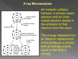
1 / 47
470 likes | 650 Views
Collider Options: Linear electron-positron (ILC). Design: Parameters & Luminosity Power Consumption and Footprint Upgrade and Staging Strategy. Marc Ross, SLAC – ILC ( with Nick Walker, DESY and Akira Yamamoto, KEK ). Energy Frontier Lepton Collider Questions:. (Abridged)

E N D
Collider Options: Linear electron-positron (ILC) Design: Parameters & Luminosity Power Consumption and Footprint Upgrade and Staging Strategy Marc Ross, SLAC – ILC ( with Nick Walker, DESY and Akira Yamamoto, KEK) Marc Ross, SLAC
Energy Frontier Lepton Collider Questions: (Abridged) 1) parameters and key characteristics? 4) power consumption and how does it scale with energy and luminosity? footprint? 5) critical technical challenges? What R&D must be done to address them and what are key demonstrations and milestones? On what timescale? What infrastructure is required? 6) What accelerator R&D is required to realized the physics opportunities in these areas? 8) Are there technology applications beyond energy frontier science that motivate development? Marc Ross, SLAC
International Linear Collider:Outline • Parameters and Layout • 250 < Ecm < 1000 GeV • Accelerator Subsystems and Footprint • SCRF Linac Accelerator R & D and Technology • Demonstrations and Key Milestones • Power consumption • Upgrades and Staging strategy Marc Ross, SLAC
International Linear Collider:Outline • Parameters and Layout • 250 < Ecm < 1000 GeV • Accelerator Subsystems and Footprint • SCRF Linac Accelerator R & D and Technology • Demonstrations and Key Milestones • Power consumption • Upgrades and Staging strategy Marc Ross, SLAC
ILC Published Parameters Luminosity Upgrade Centre-of-mass independent: Advantage of SCRF technology: long pulses N. Walker ILC PAC TDR review
ILC Published Parameters Centre-of-mass dependent: N. Walker ILC PAC TDR review
ILC Published Parameters Focus of design (and cost!) effort Centre-of-mass dependent: N. Walker ILC PAC TDR review
ILC in a Nutshell Damping Rings Polarised electron source Ring to Main Linac (RTML) (inc. bunch compressors) Beam dump 310 x football pitch e+ Main Linac Beam Delivery System (BDS) & physics detectors Polarised positronsource e- Main Linac not too scale
Ring To Main Linac (RTML) (FoDo lattice) 5 GeV 5 GeV 15 GeV 15 GeV 5 GeV 5 GeV R56 = -372 mm R56 = -55 mm ÷3 ÷6.7 bunch length: 6 mm 0.9 mm 0.3 mm beam energy: 5 GeV 4.8 GeV 15 GeV DE/E: 0.11% 1.42% 1.12% US R&D Lead: Fermilab N. Walker ILC PAC TDR review
RTML / Bunch Compressor • Emittance preservation primary challenge • fast ion instability in ~30km long return line • stray time-varying fields (≤2 nT). • spin rotation (solenoids x-y coupling) • RF and long bunch / large DE/E • wakefields, coupler kicks, cavity tilt effects… • beam based alignment • Tight requirements on phase/amplitude stability • timing at IP luminosity loss • 0.24° / 0.48° stability (correlated/uncorrelated) • LLRF challenge N. Walker ILC PAC TDR review
Central Region • 5.6 km region around IR • Systems: • electron source • positron source • beam delivery system • RTML (return line) • IR (detector hall) • damping rings • Sized for 1 TeVEcm Central Region common tunnel N. Walker ILC PAC TDR review
Central Region Example: Flat Topography The central region beam tunnel remains a complex region. Complete, detailed and integrated lattices are now available service tunnel Generic design used for geometry and generating component counts and CFS requirements. CFS (particularly CE) solutions are site-dependent!
Damping Rings Values in () are for 10-Hz mode Many similarities to modern 3rd-generation light sources US Lead: Cornell N. Walker ILC PAC TDR review
Positron Source (central region) • located at exit of electron Main Linac • 147m SC helical undulator • driven by primary electron beam (150-250 GeV) • produces ~30 MeV photons • converted in thin target into e+e- pairs yield = 1.5 not to scale! US Lead: ANL N. Walker ILC PAC TDR review
Polarised Electron Source • Laser-driven photo cathode (GaAs) • DC gun • Integrated into common tunnel with positron BDS US Leads : SLAC and JLAB N. Walker ILC PAC TDR review
BDS and MDI Geometry ready for TeV upgrade e+ source e- BDS electron Beam Delivery System US Lead: SLAC N. Walker ILC PAC TDR review
IR region (Final Doublet) • FD arrangement for push pull • different L* • ILD 4.5m, SiD 3.5m • Short FD for low Ecm • Reduced bx* • increased collimation depth • “universal” FD • avoid the need to exchange FD • conceptual - requires study • Many integration issues remain • requires engineering studies beyond TDR • No apparent show stoppers BNL prototype of self shielded quad N. Walker ILC PAC TDR review
MDI (Detector Hall) Mountainous-topography detector hall concept N. Walker ILC PAC TDR review
Emittance Preservation • Damping Ring: gey = 20nm • ~30km RTML return line • Turn around and spin rotation • Bunch compressor (two-stages) • Acceleration (10km main linac) • Positron production (e- only) • Beam delivery system (non-linear optics) • Final Doublet and collision! • Budget 15 nm gey = 35 nm at IP N. Walker ILC PAC TDR review
Tunnel Lengths and volumes Asia M. Ross, SLAC
International Linear Collider:Outline • Parameters • 250 < Ecm < 1000 GeV • Footprint Accelerator Subsystems • SCRF Linac Accelerator R & D and Technology • Demonstrations and Key Milestones • Power consumption • Upgrades and Staging strategy Marc Ross, SLAC
Site-Dependent Designs • Top-level parameters • Accelerator layout • lattice • geometry • parameters • etc. • Conventional Facilities / Siting (CFS) requirements • Central region (source, BDS, DR) • RTML (bunch compressors) • Civil engineering solutions • topography • geology • Main linac layout • RF power distribution • Klystron Cluster ‘KCS’ • Dist. Multi-Beam Klystron ‘MBK’ cost effective tunnelling methods
SCRF Linac Technology * site dependent Approximately 20 years of R&D worldwide Mature technology
ILC Cavity Assembly (Helium tank, mag. shield, tuner and coupler) Graphics by Rey. Hori
Linac building block: the Cryomodule: Graphics by Rey. Hori Marc Ross, SLAC
12 GeV cavities: overall performance CEBAF 12 GeV upgrade Vertical Test; 1500 MHz 7 cell; 10% gradient correction 72/85 @ admin limit (85%) Cavities made by RI (Germany); Followed ILC Process Reported 11.2012 by F. Pilat
RF Power Source Marx modulator 10MW MB Klystron Adjustable local power distribution system N. Walker ILC PAC TDR review
Main Linac Parameters (500 GeV) * at 31.5 MV/m N. Walker ILC PAC TDR review
MR Linac tunnel cross-section: • Personnel can occupy klystron area during operation • Radiation analysis later in presentation • Cross-over paths for egress (500 m) • 11 m wide x 5.5 m high • dimensions in mm M. Ross, SLAC
Tunnel Model: • 1:50 scale model • (KEK 2 April) M. Ross, SLAC
RF Power sources underground: Distributed Klystron Scheme accelerator cryomodules N. Walker ILC PAC TDR review
Candidate site (1 of 2) in northeastern Japan Tohoku ‘Mountain Region’ (Photo taken100 km north of Sendai.) The ILC alignment would be 50 to 400 meters below these hills. M. Ross, SLAC
Operations – Peak Power 189 KW peak delivered to average cavity • (Distributed Klystron) DKS 74% RF power to beam (189 + 67 KW generated per cavity) M. Ross, SLAC
Heat Load and Power Flow per ML unit Waste heat: • for each klystron station (surface) and • 73 kW • for each ML 3 cryomodule unit (tunnel) • 50 kW • 1.3 kW to tunnel air • 740 kW to air (ML total) • air / water fraction • 33 W/meter to air • Does not include ‘cooling’ due to cryomodules (~ 150 W 10% reduction) (KCS) Surface per ML unit Tunnel
AC Power Consumption Linac totals (MW) Asia total (MW) (mountain) M. Ross, SLAC
Collider ‘Wall Plug’ AC Power use: * 5% for operating margin, 2% for auxiliaries, 3% for HVPS and 10% for water cooling * 6 MW for 30 km beam tunnel complex M. Ross, SLAC
Parametric ‘value’ costing (KILCU): • Civil Construction: 35 / m • Utilities: 5000 / MW • Superconducting RF 180 / m (inclusive) • ‘Conventional Acc.’ 35 / m Institutional Labor is part of the project cost and must also be analyzed. M. Ross, SLAC
International Linear Collider:Outline • Parameters • 250 < Ecm < 1000 GeV • Footprint Accelerator Subsystems • SCRF Linac Accelerator R & D and Technology • Demonstrations and Key Milestones • Power consumption • Upgrades and Staging strategy M. Ross, SLAC
Staging and Upgrades: 1500 GeVE_cm 2450 bunches 1000 GeVE_cm 2450 bunches E_cm Design Baseline 500 GeVE_cm 1312 bunches 500 GeVE_cm 2620 bunches 250 GeVE_cm 1312 bunches 250 GeVE_cm 2620 bunches Beam intensity Beam Energy and Beam Power: Staging and Upgrade Strategies M. Ross, SLAC
Low Ecm Running (<300 GeV) • Positron production (yield) drops with <150 GeV • Low Ecm running (≤250 GeV) 10Hz mode • Alternate pulses for e+ production: • 150 GeV e- pulse to generate positrons • Ecm/2 e- pulse for luminosity • Ramifications: • 100ms store time in DR shorter damping times • Need to dump 150 GeV production pulse after undulator (new beamline, pulsed-magnet system) • Pulsed trajectory-correction system before undulator for 150 GeV production beam. • Electron Main Linac requires no modification • Installed AC power sufficient for ~½ energy operation at 10Hz. N. Walker ILC PAC TDR review
Luminosity Upgrade • Concept: increase nb from 1312 → 2625 • Reduce linac bunch spacing 554 ns → 336 ns • Increase pulse current 5.8 → 8.8 mA • Increase number of klystrons by ~50% • Doubles beam power ×2 L (3.6×1034cm-2s-1) • Damping ring: • Electron ring doubles current (389mA 778mA) • Positron ring: possible 2nd (stacked) ring (e-cloud limit) • AC power: 161 MW 204 MW (est.) • AC power increased by ×1.5 • shorter fill time and longer beam pulse results in higher RF-beam efficiency (44% 61%) N. Walker ILC PAC TDR review
Luminosity Upgrade Adding klystrons (and modulators) MountainTopography (DKS) Damping Ring: N. Walker ILC PAC TDR review
TeV Upgrade <26 km ? (site length <52 km ?) 1.1 km 2.2 km 10.8 km <10.8 km ? 1.3 km Main Linac BDS e+ src IP bunch comp. Assume Higher Gradient Main Linac <Gcavity> = 31.5 MV/m Geff ≈ 22.7 MV/m (fill fact. = 0.72) central region Snowmass 2005 baseline recommendation for TeV upgrade: Gcavity = 36 MV/m ⇒ 9.6 km (VT ≥ 40 MV/m) Based on use of low-loss or re-entrant cavity shapes N. Walker ILC PAC TDR review
TeV upgrade: Construction Scenario 500GeV operations start civil construction Main Linac BDS BC e+ src IP civil construction + installation 500GeV operations BC Main Linac BDS e+ src IP Installation/upgrade shutdown BC Main Linac BDS e+ src IP final installation/connection removal/relocation of BC Removal of turnaround etc. Installation of addition magnets etc. Commissioning / operation at 1TeV BC Main Linac BDS e+ src N. Walker ILC PAC TDR review IP
TeV Parameters (2 sets) PAC constrained ≤300 MW shorter bunch length(within BC range) horizontal focusing main difference low and high beamstrahlung
ILC at low/high Ecm • Low Ecm operation of upgraded ILC: • L250 ~ 3e34; Wall plug 200 MW • Higgs Factory Option • High Ecm ~ 1.5 TeV • L1500 ~ 6e34; Wall plug 340 MW Marc Ross, SLAC