IP technology
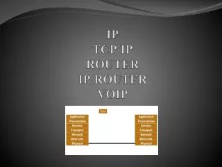
IP technology. 1) IP technology basic concepts 2) The IP protocol stack 3) Transport layer protocols (UDP, TCP, SCTP) 4) The IP datagram header (IPv4 and IPv6) Addressing and routing 6) GPRS. IP network architecture. Router. Host. Computer. Public Internet. Host. LAN or intranet.

IP technology
E N D
Presentation Transcript
IP technology • 1) IP technology basic concepts • 2) The IP protocol stack • 3) Transport layer protocols (UDP, TCP, SCTP) • 4) The IP datagram header (IPv4 and IPv6) • Addressing and routing • 6) GPRS
IP network architecture Router Host Computer Public Internet Host LAN or intranet Host can be behind modem or ADSL connection Host Host ARP
Client-server concept Host Host Client Server Request Response : Transactions are always started by client Network does not have to know IP address of client before transaction (dynamic IP address allocation is possible) Web (www) applications are based on this concept
Role of routers in an IP network Host Host Router Client Server Routers perform switching of IP packets (task of the OSI network layer) IP packets are routed independently through the IP network(s) towards the destination indicated by the destination IP address in the IP datagram header Independent routing => connectionless service (IP packets belonging to a certain transaction can travel along different paths, experience different delays, and arrive out of sequence at the destination…)
IP protocol suite HTML RT Data Signalling Protocols (e.g. ISUP) SMTP POP, IMAP FTP HTTP DNS RTP TCP UDP SCTP IP ICMP RIP OSPF BGP SLIP PPP ARP LAN-protocols, ATM, PSTN/ISDN, PLMN …
Lower protocol layers IP ICMP RIP OSPF BGP SLIP PPP ARP Bearer Technology LAN-protocols, ATM, PSTN/ISDN, PLMN … ARP (Address Resolution Protocol) takes care of mapping between logical IP addresses and physical MAC addresses in a Local Area Network (LAN). PPP (Point-to-Point Protocol) or SLIP (Serial Line IP) is used for transport of IP traffic over modem connections between terminal and ISP’s Point of Presence (PoP).
Assisting protocols in the IP layer (1) TCP UDP SCTP IP ICMP RIP OSPF BGP SLIP PPP ARP ICMP (Internet Control Message Protocol) is a mandatory protocol (i.e. must be supported by all routers) and is used for informing hosts about problems in the network. Some ICMP messages: destination network/host/port unreachable/unknown, echo request, echo reply, TTL expired, IP header bad.
Assisting protocols in the IP layer (2) TCP UDP SCTP IP ICMP RIP OSPF BGP SLIP PPP ARP Various routing protocols are employed for exchanging information between routers in the IP network RIP (Routing Information Protocol) OSPF (Open Shortest Path First) BGP (Border Gateway Protocol) for routing within autonomous systems for “international” routing
Transport layer protocols (1) HTML RT Data Signalling Protocols (e.g. ISUP) SMTP POP, IMAP FTP HTTP DNS RTP TCP UDP SCTP IP ICMP RIP OSPF BGP TCP (Transmission Control Protocol) takes care of end-to-end flow & error control + segmentation & reassembly of larger blocks of information. UDP (User Datagram Protocol) is used for ”unreliable but fast” transport of independent blocks of information.
Transport layer protocols (2) HTML RT Data Signalling Protocols (e.g. ISUP) SMTP POP, IMAP FTP HTTP DNS RTP Adapt. pr. TCP UDP SCTP IP ICMP RIP OSPF BGP SCTP (Stream Control Transmission Protocol) is an alternative to TCP (=> too slow) or UDP (=> not reliable), primarily for carrying signalling information. SCTP may become popular also more generally in the future. See: http://www.isoc.org/briefings/017/index.shtml
SCTP is used for signalling transport Signalling Protocol (e.g. ISUP) MTP Adapt. pr. Sigtran protocols Protocol conversion in signalling gateway (SGW) SCTP IP Phys. Transport of SS7 application protocols (e.g. ISUP) over conventional SS7 network using MTP. Transport of SS7 application protocols over IP using Sigtran protocol stack (which includes SCTP).
Four advantages of SCTP over TCP SCTP TCP Preservation of message boundaries (SCTP carries blocks of information) Multistreaming property (several streams in parallel) Multihoming property (the host has several points of attachment to the Internet) Protection against SYN flooding attacks TCP carries a continuous stream of information (bad for message transport) One continuous stream only (head-of-line blocking possible) One point of attachment only (makes TCP less reliable) SYN flooding attacks are a problem in TCP
Preservation of message boundaries TCP ... ... Information is carried as a continuous stream of bytes. The higher protocol layers must find the message boundaries at the receiving end, TCP cannot do this. SCTP ... ... SCTP can find the message boundaries at the receiving end of the SCTP connection. Higher protocol layers do not have to do this.
Multisreaming TCP 1 ... ... 2 2 2 A message is delayed or lost (1). All other messages of all other users (2) are delayed (=> head-of-line blocking). SCTP 2 1 ... ... If a message is delayed or lost (1), only messages belonging to this stream are delayed (2). Other messages are part of other SCTP streams and are carried without delay over the SCTP connection (also called SCTP association).
Multihoming In a TCP connection, only one IP address is available at each endpoint. Client Server 123.456.7.89 123.987.6.54 In an SCTP connection, several IP addresses are available at each endpoint. Client Server 123.456.7.89 123.456.6.78 123.456.5.67 123.987.6.54 123.987.5.43 123.987.4.32 If not available use instead
Protection against SYN flooding attacks TCP uses a three-way handshake to set up a connection. This method is prone to SYN flooding attacks. Client Server SYN SYN/ACK ACK If client first sends SYN, but does not then send ACK, this TCP connection is left hanging... SCTP uses a 4-way handshake with a signed cookie, in this way preventing DoS (Denial-of-Service) attacks like SYN flooding.
Applications (1) HTML RT Data Signalling Protocols (e.g. ISUP) SMTP POP, IMAP FTP HTTP DNS RTP TCP UDP SCTP FTP (File Transfer Protocol) for sending larger files (offers flow and error control). SMTP (Simple Mail Transfer Protocol) for outgoinge-mail. POP (Post Office Protocol) or IMAP (Internet Message Access Protocol) for fetching e-mail from mailbox.
Applications (2) HTML RT Data Signalling Protocols (e.g. ISUP) SMTP POP, IMAP FTP HTTP DNS RTP TCP UDP SCTP HTTP (HyperText Transfer Protocol) is used for client-server type of communication, and is the most popular protocol for transport of WWW content (e.g. HTML pages). http://www.hut.fi/overview.html Uniform Resource Locator (URL) network & protocolhost computer content page written in HTML
Applications (3) HTML RT Data Signalling Protocols (e.g. ISUP) SMTP POP, IMAP FTP HTTP DNS RTP TCP UDP SCTP DNS (Domain Name System) performs translation between IP addresses and domain names: 122.233.121.123 thisnetwork.thishost.com IP address must be used for routing through IP networks However, domain names are more user friendly
Applications (4) HTML RT Data Signalling Protocols (e.g. ISUP) SMTP POP, IMAP FTP HTTP DNS RTP TCP UDP SCTP RTP (Real Time Protocol) provides important functions (e.g. sequence numbering, time stamp) for transport of real time data. RTP runs on top of UDP. RTP can carry e.g. • Digitized speech (PCM) • Encoded speech (EFR, AMR) • Multimedia traffic • (compressed audio, video)
Real Time Protocol (RTP) • RTP is used for carrying real-time data (e.g. coded voice) over IP networks. RTP offers two features: • The correct RTP packet order is maintained at the destination • RTP packets include a time stamp that records the exact time of transmission. Voice stream RTP UDP IP : Time stamps can be used at the destination to ensure synchronised play-out of (e.g.) the voice samples. TCP cannot be used below RTP, since TCP causes too large delays. Unfortunately, unlike TCP, UDP cannot guarantee correct packet order at the destination.
RTP avoids delay variation It is worth noting that RTP cannot reduce the total transmission delay in the network. However, the usage of time stamps helps to reduce the time variation or jitter at the destination. RTP in itself cannot reduce the time variation. This is the task of the application (which utilises the time stamps provided by RTP) at the destination. RTP is able to carry a large variety of coded information (audio or video) => RTP is the standard solution for VoIP applications (“Voice over RTP over UDP over IP”).
IPv4 header structure (1) 32 bits (= 4 bytes or octets) Version IHL Type of Service Total length of IP datagram Identification Flags Fragment offset Time-to-live Protocol Header checksum (for error control) Source IP address Destination IP address Options Padding Payload of IP datagram Version (4 bits): tells that this is IP Version 4 (IPv4) (In case of IPv6, the bits following the 4-bit Version field should be interpreted totally differently)
IPv4 header structure (2) Version IHL Type of Service Total length of IP datagram Identification Flags Fragment offset Time-to-live Protocol Header checksum (for error control) Source IP address Destination IP address Options Padding Payload of IP datagram IP header length (4 bits) is needed since Options+Padding can vary in length. Usually IP header length = 20 bytes. (The Options field is rarely used. This is why such a field is not included in the IPv6 header)
IPv4 header structure (3) Version IHL Type of Service Total length of IP datagram Identification Flags Fragment offset Time-to-live Protocol Header checksum (for error control) Source IP address Destination IP address Options Padding Payload of IP datagram ToS = Type of Service (8 bits) is used for QoS management purposes (=> DiffServ). (In the IPv6 header there is an 8 bit Traffic class field for the same purpose)
IPv4 header structure (4) Version IHL Type of Service Total length of IP datagram Identification Flags Fragment offset Time-to-live Protocol Header checksum (for error control) Source IP address Destination IP address Options Padding Payload of IP datagram Datagram length (16 bits): since this field is 16 bits long, the IP datagram can contain up to 216 = 65535 bytes (in theory). Most routers, however, cannot handle such large datagrams.
IPv4 header structure (5) Version IHL Type of Service Total length of IP datagram Identification Flags Fragment offset Time-to-live Protocol Header checksum (for error control) Source IP address All fragments contain the same number Has value zero in last fragment Position of fragment in original datagram Destination IP address Options Padding Payload of IP datagram IP fragmentation: a large IP datagram may be fragmented (in any router along the path) and will be reassembled at the destination. IPv6 does not offer fragmentation (it is rarely used anyway).
IPv4 header structure (6) Version IHL Type of Service Total length of IP datagram Identification Flags Fragment offset Time-to-live Protocol Header checksum (for error control) Source IP address Used also in IPv6 (called “hop limit”) Destination IP address Options Padding Payload of IP datagram Time-to-live (8 bits): this number is decreased by one in each router along the path. If number zero is reached in a router, the IP datagram is discarded and the router sends an ICMP message (TTL expired) to the source of the datagram.
IPv4 header structure (7) Version IHL Type of Service Total length of IP datagram Identification Flags Fragment offset Time-to-live Protocol Header checksum (for error control) Source IP address Used also in IPv6 (called “next header”) Destination IP address Options Padding Payload of IP datagram Starts here ... Protocol field (8 bits): describes which higher layer protocol is used (TCP, UDP, or SCTP). The header of the higher-layer datagram is located at the beginning of the IP datagram payload.
User/application data TCP/UDP header TCP/UDP datagram IP header IP datagram Bearer protocol frame/packet/cell IP packet structure Direction of transport
IPv4 header structure (8) Version IHL Type of Service Total length of IP datagram Identification Flags Fragment offset Time-to-live Protocol Header checksum (for error control) Source IP address Destination IP address Options Padding Payload of IP datagram Header checksum (16 bits): used for error control. Routers along the path have to recalculate the checksum. This kind of error control is not used in IPv6 (since the same error control function is offered by TCP - and even UDP). Why?
IPv4 header structure (9) Version IHL Type of Service Total length of IP datagram Identification Flags Fragment offset Time-to-live Protocol Header checksum (for error control) Source IP address Destination IP address Options Padding Payload of IP datagram Source and destination IP address (32 bits each): note that these addresses are not changed in routers along the route. In IPv6 the addresses are 4 x 32 = 128 bits long!
IPv6 header structure 32 bits (= 4 bytes or octets) Version Traffic class Flow label (identifies datagram ”flows”) Payload length Next header Hop limit Source IP address Can point to an “options” field in the payload (instead of TCP, UDP …) Destination IP address Payload of IP datagram
IPv4 and IPv6 address structure IPv4 address(32 bits or 4 bytes): 123.45.67.89 One byte (number between 0 and 255) IPv6 address (128 bits or 16 bytes): 2001:0db8:85a3:0000:1319:8a2e:0370:7344 Four hexadecimal numbers (between 0 and f), each occupying four bits.
Strong points of IPv6 Larger IP address space (3.4 1038 IP addresses available) Fixed IP datagram header length (no variable length options field …) and better way to handle options More simple (and therefore faster) header processing; no checksum checking or fragmentation Real-time service or QoS support (using ”flow label” and ”traffic class” fields) .
UDP header structure Destination port number Source port number Length of UDP content (incl.header) Checksum UDP payload (application data) Two functions of UDP: • application multiplexing (using • port numbers) • error control (using checksum)
TCP header structure Destination port number Source port number Sequence number Flow control Acknowledgement number Data offset Flags Receiver window size Checksum Urgent pointer Options Padding TCP payload (application data) Starts here ... Flags are one-bit indicators (SYN, ACK, FIN ...) used for simple signalling (TCP connection setup and teardown)
Difference between IP address and port Host A IP address – points to host Port – points to application Host B Port Y Port Z IP datagram contains: (in IP header) source IP address N destination IP address M (in TCP/UDP header) source port Y destination port Z TCP/UDP TCP/UDP IP IP IP address N IP address M
Some important port numbers (Just to give an example, not necessary to remember.) http (web applications) 80 TCP only https (http over SSL) 443 TCP only DNS 53 UDP mainly SMTP (outgoing mail) 25 TCP/UDP POP3 (from mail server) 110 TCP only IMAP (from mail server) 220 TCP/UDP (Within the server only. The client can usually freely choose its port number.) IP address + port number is given as 123.456.7.89:80
Hierarchical structure: unnecessary capacity 27 = 128 224 = 16.8 106 Class A 0 Network Host 214 = 16384 216 = 65536 Class B 10 Network Host 221 = 2.1 106 28 = 256 Class C 110 Network Host running out of class B networks ! Flat structure would provide 232 = 4.3 109 IP addresses IPv6 provides 2128 = 3.4 1038 IP addresses ! IPv4 address structure
Insufficient IPv4 address space There are basically four ways to avoid running out of IP addresses, either by making more efficient usage of the available address space (point 1) or by “expanding” the address space (points 2 – 4): 1. 2. 3. 4. Classless interdomain routing (CIDR) Dynamic IP address allocation Network address translation (NAT) Move to IPv6 (=> virtually unlimited address space).
Classless interdomain routing (CIDR) In comparison with the original class-oriented address structure, CIDR makes more efficient usage of the available address space. The size of the network part of the address is included in the IP address after the slash: 182.46.92.110/21 10110110 001011100101110001101110 Network part = 21 bits Host part = 32 – 21 = 11 bits In this example, eight class C networks are effectively grouped into one larger network.
Dynamic IP address allocation IP address is allocated temporarily. Address is taken from an address pool (stored in a DHCP server) and after usage is returned to the address pool. Applications: Dial-up (modem) Internet access ADSL GPRS WLAN Protocol used: DHCP (Dynamic Host Configuration Protocol, RFC 2131).
Network address translation (NAT) NAT is a method of connecting a number of hosts (in a private network) to the Internet using a single external IP address. Private network Internet NAT gateway 10.123.4.11 Port no. 1 123.456.7.89 10.123.4.12 Port no. 2 10.123.4.13 Port no. 3 Reusable IP addresses (for instance of form 10.x.x.x or 192.168.x.x) are used for routing "behind" the NAT gateway. A single (globally unique) IP address is used for routing through the Internet. Hosts are identified by TCP/UDP port numbers.
IP address and port usage in NAT In outgoing packets (from client to server), NAT affects the source IP address and port number: IP header TCP/UDP header … … … S IP addr. D IP addr. S port nr. D port nr. For example: For example: 10.123.4.11 => 123.456.7.89 1123 => 12515 In incoming packets, the destination IP address and port number are affected: … … … S IP addr. D IP addr. S port nr. D port nr.
Hierarchical structure of Internet EGP = Exterior Gateway Protocol AS = Autonomous System AS 1 IGP EGP AS 3 AS 2 IGP = Interior Gateway Protocol IGP
Routing protocols in Internet In practice, there is worldwide only one very complex EGP, namely BGP (Border Gateway Protocol) The two most well-known IGP’s are RIP and OSPF OSPF (Open Shortest Path First) RIP (Routing Information Protocol)
RIP vs. OSPF RIP is a distance vector routing protocol, where neighbouring routers exchange routing information. RIP is one of the oldest IGPs and is still widely used today. RFC 1723 OSPF is a link-state routing protocol, where routers construct a complete topological map of the entire autonomous system. Autonomous system can be hierarchically structured into smaller “networks”. Open => publicly available (not like Cisco’s EIGRP) RFC 2178
Example: downloading HTML page (1) User terminal (Client) HTML page source (Server) Send me HTML page HTTP HTTP Internet service provider’s PoP TCP TCP IP IP IP PPP PPP ATM ATM Modem connection and PPP link between user terminal and ISP’s Point of Presence (PoP) is established. User terminal is given IP address (dynamic allocation).
Example: downloading HTML page (2) DNS replies ... User terminal (Client) HTML page source (Server) UDP IP Contact DNS ... UDP UDP IP IP IP PPP PPP DNS performs translation between URL and IP address of server (only the latter can be used for routing IP packets to the server).