Download

1 / 24
240 likes | 256 Views
This article explores the communications infrastructure needed for the SKA project, focusing on optimizing data transport and processing. It investigates different data communications interface types and proposes a scalable architecture based on industry standards. The article also discusses the use of commercially available equipment to minimize costs.

E N D
The SKA from a Communications Infrastructure Perspective Charles Smith Commonwealth Scientific and Industrial Research Organisation Cnr., Vimiera and Pembroke Roads Marsfield, New South Wales 2122 Australia charles.smith@csiro.au
The SKA from a Communications Infrastructure Perspective The SKA design process can be seen as an exercise in optimizing the transport and processing of very large volumes of data” “It is desirable to be able to minimize design and construction costs by using commercially available equipment where possible, to exploit Moore’s Law and available commercial products” K. Van Der Schaff, R. Overeem “COTS Correlator Platform” Experimental Astronomy, vol 17, pp. 287-297, 2004
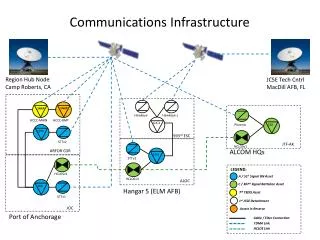
Topics of Discussion A large component of the SKA will be the communications infrastructure required to interconnect the sensors and other elements of the system. Data communications interface types are investigated for possible adoption in the SKA . A resulting industry standards based, scalable data communications architecture for the SKA is then introduced. Discussions here are based upon the published STAN High Level Description WP2.030.030.030-TD-001 - 3 May 2011
Proposed SKA 1 Sensor Types Single Pixel Feed (SPF) - 250 450 MHz -3 GHz Single Dual Pole Beam / Dish 2 x 1 GHz Bandwidth 24 Gb/s / Dish Low Freq Sparse Aperture Array (AA-Low) - 50 70-450 MHz 160 Dual Pole Beams / Station 160 x 2 x 380 MHz Bandwidth 1216 Gb/s / Station Phased Array Feed (PAF) - 250 600 MHz – 1.5 GHz 43 Dual Pole Beams / Dish 43 x 2 x 900 MHz Bandwidth 928.8 Gb/s / Dish
Proposed SKA 2 Sensor Types Single Pixel Feed (SPF) - 3000 300 MHz - 10 GHz Single Dual Pole Beam / Dish 9 x 2 GHz Bandwidth 216 Gb/s / Dish Low Freq Sparse Aperture Array (AA-Low) - 250 70-450 MHz 4400 Dual Pole Beams / Station 4400 x 2 x 380 MHz Bandwidth 3344 Gb/s / Station Phased Array Feed (PAF) - ~2500 600 MHz – 1.5 GHz 43 Dual Pole Beams / Dish 43 x 2 x 900 MHz Bandwidth 928.8 Gb/s / Dish High Freq Dense Aperture Array (AA-Mid) - 250 400 MHz – 1.4 GHz 1200 Dual Pole Beams / Station 1200 x 2 x 700 MHz Bandwidth 16800 Gb/s / Station (17 Tb/s)
Single Pixel Feed (SPF) SKA Phase 1 450 MHz-3.0 GHz Samples 450 MHz-3.0 GHz Samples OR Custom A/D Bridge Custom A/D Bridge 1 GHz Bandwidth 24Gb/s 1 GHz Bandwidth 24Gb/s COTS Interface COTS Interface 3 × 10G Framed Transmission 1 × 40G Transmission Interface Types Analogue Digital COTS
Single Pixel Feed (SPF) SKA Phase 2 300 MHz-10 GHz Samples 300 MHz-10 GHz Samples Custom A/D Bridge Custom A/D Bridge 9 GHz Bandwidth 216Gb/s 9 GHz Bandwidth 216Gb/s COTS Interface COTS Interface 3 × 100G Framed Transmission 22 × 10G Framed Transmission
Phased Array Feed (PAF) Custom A/D Bridge Beamformer Custom A/D Bridge Beamformer Custom A/D Bridge Beamformer 0.6-1.5 GHz Samples 0.6-1.5 GHz Samples 43 Beams x 0.9 GHz 928.8 Gb/s 43 Beams x 0.9 GHz 928.8 Gb/s Antenna Aggregation Fabric Antenna Aggregation Fabric Antenna Aggregation Fabric 93 × 10G Framed SONET/SDH, FC or Ethernet 24 × 40G Framed SONET/SDH, FC or Ethernet 10 × 100G Framed FC or Ethernet
Sparse Aperture Array - AA-Low SKA Phase 1 160 Beams x 380 MHz 1216 Gb/s Custom A/D Bridge Beamformer Custom A/D Bridge Beamformer 483 × 2.5G Time Slices 122 × 10G Frames Antenna Aggregation Fabric Antenna Aggregation Fabric 31 × 40Gor 13 × 100G Transmission 31 × 40G Transmission SONET/SDH Ethernet or Fiber Channel
Choosing an Industry Standard Interface for Sensors Output data rates across the differing sensor technologies vary widely. Industry standards for digital data transmission that can satisfy the sampling requirement rates identified are SONET/SDH, Ethernet, and Fibre Channel. Each have the capabilities to support the individual streams from sensors with interface addressing, multiplexing and aggregation to identify, encapsulate and reliably transmit the data. They are supported in short haul high density Local Area Networks (LAN), Wide Area Network (WAN) aggregation interconnects and capable of long haul transmission via DWDM systems.
Infiniband Options & Capabilites The Infiniband protocol and interface is currently limited to high-speed interconnections between nodes within close proximity and Data Centres. It is a reasonable choice to investigate for use within the SKA correlation and supercomputing environments. It is not an appropriate choice for the sensor to COTS interface given its distance limitations & current requirement to be subsequently bridged to other COTS technologies for wider transmission.
Development of Sensor to COTS Interfaces For all sensor technologies, bridges between the streaming sensors and COTS transmission interfaces will need to be developed by the SKA community. Industry standards would need to provide for the unidirectional nature of sensor traffic.
SONET/SDH as a sensor to COTS Interface Minimising the number of transmission COTS Interfaces can be achieved via statistical multiplexing in SONET/SDH. The higher layer protocol would need to provide a non-blocking buffering, aggregation and switching capability of multiple services onto a higher speed 10G or 40G uplink. For a standards based solution a layer 3 routing capability is required and IP is the obvious choice. The additonal cost involved in implementing a Layer 3 Intelligence is however the true restricting factor in selecting this method.
Ethernet & Fiber Channel as a sensor to COTS Interface Ethernet and Fibre Channel both provide capabilites for non-blocking switching and aggregation functions. The both have standards defined mechanisms using quality of service, inter-frame gaps and port buffering to maximise the average inbound frame rates to the aggregated higher speed 40G or 100G outbound interfaces. At this point in time the Ethernet Standard only has unidirectional functionality covered in the 100 Megabit Standard. The unidriectional capability will need to be brought to the IEEE for ratification of 10 Gigabit, 40 Gigabit & 100 Gigabit Ethernet and Fiber Channel standards to ensure multi-vendor interoperation.
Fiber Channel as a SKA Sensor COTS Interface Fibre Channel suits simple aggregation functions but needs to be planned and expanded very carefully as the native protocol is blocking based. The standard demands a transmitted frame be delivered and will block other traffic until it has been delivered. This does guarantee delivery of every frame however if there is an imbalance in the system then the link will block. The buffer credit mechanism is used to offset this issue, however it requires careful design of each link in the network and which varies based upon distance and propagation.
Ethernet as a SKA Sensor COTS Interface Ethernet provides for a common Layer 2 interface across all sensor types. It is also a common interface between sensors and the beamforming / correlation compute tasks. Expected growth in sensor rates for SKA Phases 2 and 3 are catered for with the introduction of 40GigE and 100GigE while allowing SKA Phase 1 systems to co-exist and grow. It allows for the upstream optimization of traffic throughput and flexible growth by integrating individual interface under-subscriptions by utilizing switching aggregation fabrics, port buffering/queing & QoS mechanisms.
Ethernet as a SKA Sensor COTS Interface Server interconnections are moving to native support for 10GigE and are becoming available at 40GigE by 2014 and 100GigE by 2020.
Ethernet as a SKA Sensor COTS Interface Accelerated annual port sales forecast vs. the drop in average sales price over the next 4 years show 10GigE to be a cost effective technology to base SKA Phase 1 A-D sensor outputs as the COTS interface of choice
Ethernet as a SKA Sensor COTS Interface The defined standard of 40GigE & 100GigE, (IEEE Std 802.3ba-2010) allows for the smooth transition and upgrade path of today’s networks. SKA Phase 2 will require 100 Gigabit aggregation & transmission capabilities to support the proposed increases in sensor bandwidth. Ethernet standards are very well understood across the communications industry, the scientific community, the engineering sectors and business sectors as it has proven price/performance and a predicted growth pattern.
SPF SKA Phase 1 250 × 450 MHz-3.0 GHz Samples 450 MHz-3.0 GHz Samples Custom A/D Ethernet Bridge Custom A/D Ethernet Bridge 3 × 10GbE Transmission 3 × 10GbE Transmission Switching & Aggregation Fabrics 750 x 10Gbe to 60 x 100GbE Fabric reduces 750 10GbE to 60 100G Interfaces 60 × 100GigE Transmission DWDM Aggregation 1 Pair Fibres 80 Channels / Pair 100GbE / Channel Correlator
PAF SKA Phase 1 250 × 43 Beams x 0.9 GHz 928.8 Gb/s Custom A/D Ethernet Bridge Beamformer Custom A/D Ethernet Bridge Beamformer 93 × 10GbE Antenna Aggregation Fabric Antenna Aggregation Fabric 93 × 10GbE 10 × 100GbE Transmission 10 × 100GbE Transmission Fabric reduces 2,500 to 2322 100G Interfaces 30 Pairs Fibre 80 Channels / Pair 100GbE / Channel Switching & Aggregation Fabrics 2500 x 100GbE to 2322 x 100GbE 2322 × 100GigE Transmission Correlator
AA-Low SKA Phase 1 50 × 160 Beams x 380 MHz 1216 Gb/s Custom A/D Ethernet Bridge Beamformer Custom A/D Ethernet Bridge Beamformer 130 × 10G Transmission Antenna Aggregation Fabric Antenna Aggregation Fabric 13 × 100G Transmission Fabric reduces 650 to 608 100G Interfaces Optical DWDM Aggregation 8 Pairs Fibre 80 Channels / Pair 100GbE / Channel 608 × 100GigE Transmission Correlator
SKA Phase 1 Custom Development & COTS Capabilities SPF 250 x PAF 250 x SAA 50 x Custom Development 30 x 2 × 7Gb ⁄ s Streams 2 × 12Gb ⁄ s Streams 480 x 2 × 3.8Gb ⁄ s Streams Possible COTS Supplied 50 x 130 × 10GbE 250 x 3 × 10GbE 93 × 10GbE Transmission 38 x 80 × 100G DWDM Antenna Aggregation Fabrics Antenna Aggregation Fabrics 250 x 10 × 100GbE 13 × 100GbE Site Switching & Aggregation Fabrics 38 Pairs Fibre Site Switching & Aggregation Fabrics 3040 x 100GbE 608 × 100GbE Transmission Core Facility Correlation M&C 60 × 100GbE Transmission 2322 × 100GbE Transmission
Summary Industry has switching and transmission systems in-place that will satisfy the SKA raw data communications requirements for Phase 1 of the project today and standards are being ratified to satisfy the requirements for Phases 2 and 3. Intelligence in bandwidth aggregation capabilities coupled with systems growth support is a critical factor for building a scalable SKA. Selecting a standards based well-understood communications interface allows for the close liason across vendors & industry with systems engineering and the astronomy research communities.