Download

1 / 29
350 likes | 669 Views
Explore the process of creating high-level state machines and datapaths for laser-based distance measurers. Learn how to connect and derive controllers' FSM, build digital filters, and develop FIR filters with block diagrams and templates. Dive into video compression principles and signal filtering techniques.

E N D
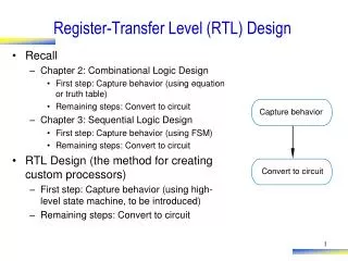
Digital Design – Register-Transfer Level (RTL) Design Chapter 5 - Register-Transfer Level (RTL) Design
Digital DesignRTL Design Table 5.1 RTL Design Process
Digital DesignRTL Design Figure 5.1 Laser-based distance measurement. Figure 5.2 Block diagram of the laser-based distance measurement system. Example 5.1 Laser-based distance measurer.
Digital DesignRTL Design Step 1: Create a high-level state machine Example 5.1 Laser-based distance measurer.
Digital DesignRTL Design Step 2: Create a datapath Example 5.1 Laser-based distance measurer.
Digital DesignRTL Design Step 3: Connect the datapath to a controller
Digital DesignRTL Design Step 4: Derive the controller’s FSM Example 5.1 Laser-based distance measurer.
Digital DesignRTL Design Figure 5.7 FSM description of the controller for the laser-based distance measurer, using the convention that FSM outputs not explicitly assigned a value in a state are implicitly assigned 0
Digital DesignRTL Design Figure 5.8 A basic digital filter that outputs the average of the previous four inputs, assuming the input was steady at 180 for a long time before the above sequence began, and stays at 182 for a long time after the sequence.
Digital DesignRTL Design Figure 5.9 Writing the four registers in a round-robin manner to always maintain the previous four input values in the registers.
Digital DesignRTL Design Figure 5.10 Datapath (right) and FSM description of the controller (left) for our basic filter.
Digital DesignRTL Design Figure 5.11 High-level state machine of the sending half of a simple bus interface.
Digital DesignRTL Design Figure 5.12 Bus interface timing diagram.
Digital DesignRTL Design Figure 5.13 Datapath (right) and controller FSM description (left) for the simple bus interface.
Digital DesignRTL Design Figure 5.14 A key principle of video compression recognizes that successive frames have much similarity.
Digital DesignRTL Design Figure 5.15 Sum-of-absolute-differences (SAD) component: block diagram (left), and high-level state machine (right).
Digital DesignRTL Design Figure 5.16 SAD datapath and controller FSM.
Digital DesignRTL Design Figure 5.17 Results of a 5-tap FIR filter with c0=c1=c2=c3=c4=0.2 applied to a noisy signal.
Digital DesignRTL Design Figure 5.18 Adding a main signal, in1, to a carrier signal, in2, resulting in a composite signal in_total.
Digital DesignRTL Design Figure 5.19 Filtering out the carrier signal using a 7-tap FIR filter with constants 0.25, 0, 0, 0.5, 0, 0, 0.25. The slight delay in the output signal typically poses no problem.
Digital DesignRTL Design Figure 5.20 General block diagram of an FIR filter.
Digital DesignRTL Design Figure 5.21 Beginning to build the datapath for the FIR filter -- inserting and connecting the x(t), x(t-1) and x(t-2) registers.
Digital DesignRTL Design Figure 5.22 Extending the datapath for the FIR filter -- inserting and connecting the c0, c1, and c2 registers, along with the multipliers, for each tap.
Digital DesignRTL Design Figure 5.23 Computing the output Y in the FIR filter as the sum of the tap products.
Digital DesignRTL Design Figure 5.24 Finalizing the FIR filter datapath with circuitry for loading the constant registers.
Digital DesignRTL Design Figure 5.25 C program description of a sum-of-absolute differences computation -- The C program may be easier to develop and easier to understand than a state machine.
Digital DesignRTL Design Figure 5.26 T for assignment statement. Figure 5.27 Template for if-then statement. Figure 5.28 Template for if-then-else statement. Figure 5.29 Template for while loop statement.
Digital DesignRTL Design Figure 5.30 Behavioral-level design starting from C code.
Digital DesignRTL Design Figure 5.31 Behavioral-level design of the sum-of-absolute difference code.