Download
1 / 22
220 likes | 245 Views
This article discusses the NCEP ESMF GFS global spectral forecast system, which is based on the ESMF version of the operational GFS system. It provides an overview of the system's structure, including the ESMF superstructure and infrastructure utilities. The steps to create the NCEP ESMF GFS system are outlined, along with future plans for developing other ESMF systems at NCEP.

E N D
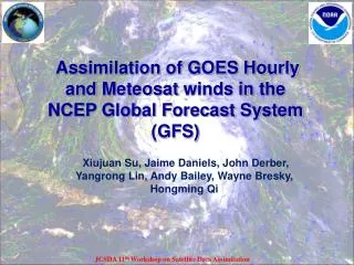
NCEP ESMF GFS Global Spectral Forecast Model Weiyu Yang, Mike Young and Joe Sela ESMF Community Meeting MIT, Cambridge, MA July 21, 2005
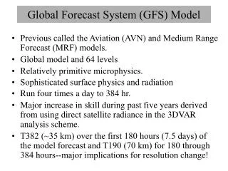
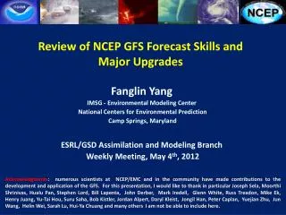
The Version of the NCEP ESMF GFS System • The NCEP ESMF GFS global spectral forecast system is the ESMF version of the current NCEP operational GFS system which started its operational run on May 31, 2005. • The detailed GFS documentation is at: http://www.emc.ncep.noaa.gov/modelinfo/index.html
Use the latest ESMF software version, ESMF - 2.1.1. • The outputs of the ESMF GFS system is identical to the results of the original GFS system.
Structure of the NCEP ESMF GFS System • This system uses the ESMF superstructure for its top levels. It uses the ESMF Virtual Machine (VM), Grid Component, Set Service, Grid, DELayout, ESMF interface States and Internal State. • It uses three ESMF Infrastructure utilities, Config, Time Manager and Log Error.
Superstructure of the NCEP ESMF GFS System • Use ESMF VM with default 1-1 DELayout. • ESMF internal state contains all necessary information to control the model running and to restart the run. • Whole ESMF interface package which contains every possible GFS import and export fields as well as the diagnostic fields to link different applications.
Every single ESMF import and export variable field has its own switch flag, which can turn on or turn off, to flexible link to different applications. If just run the stand alone GFS, all flags may be turned off to save computational cost and storage.
Since ESMF has no standard interface state yet for the spectral coefficient fields, I use the regular FORTRAN array ESMF interface to present the spectral coefficient array to create the spectral interface state. All ESMF interface states are just used for linking out side applications. The internal parallel decomposition design is not changed to keep its original performance.
There are four different types of ESMF grid in the NCEP ESMF GFS system. They are for the single level spectral fields (such as Ps, Zs), the multiple level spectral fields(such as wind, T, q etc.), the Gaussian grid (such as all surface process data) and the date, time information. All ESMF interfaces use the default 1-D DELayout distribution.
Three ESMF Infrastructure Utilities • There are three ESMF Infrastructure Utilities in the NCEP ESMF GFS system: • ESMF Config; • ESMF Time Manager; • ESMF LogError.
ESMF Config • Use a single ESMF config file to input all three namelists of the original GFS model. • Config file also contains all switch flags of the ESMF interface states. • Every single Config parameter read-in is checked by the ESMF LogError to make sure all the config processes to be successful.
ESMF Time Manager • Use the ESMF Time Manager to manage the GFS model time related variables. • Use ESMF Time and ESMF Time Interval variables to define the start time, end time, running duration length to control the GFS integrating. No explicit run do loop appears in the top level superstructure routines.
ESMF LogError • Use the default ESMF LogError. • Multiple output files for each processor. • Log output info set up at every important running point to help debug processes. • Log Error check points are set up when calling every ESMF routine and many other subroutines.
Steps to Create the NCEP ESMF GFS System • Restructure the original GFS model to create a GFS ESMF – ready version. • Develop the ESMF superstructure of the ESMF GFS system. • One by one put in the ESMF infrastructure utilities.
Restructure the Original GFS Model • The first step to create the ESMF version of GFS model is restructuring of the original GFS to make it to be a component - subroutine level callable. • Initialize, run and finalize are separated and define the internal state which contains all necessary information to restart the model run.
Move the I/O of the import state out of the Run routine, to prepare the ESMF interface states. • Use a single main drive routine to control the model run. • Use single executable for different resolution running. Original GFS needs to re-compile.
Removed the common blocks and use module for the future run concurrency requirement.
Some ESMF Systems Required to Develop in NCEP • ESMF version of the NCEP Data Analysis System. • Create the coupler to link to NCEP data analysis system to make the operational cycling run. • Create the coupler to link the ESMF GFS model with GFDL MOM-4 Ocean Model. • Create the concurrent run version of the NCEP ESMF GFS system for NCEP Ensemble operational forecasting.
Final Goal of the ESMF in NCEP • Make every single model, such as the surface process model, ocean model, regional forecast model, etc. to be the ESMF version. • Combine all single NCEP ESMF model to create a whole concurrency run package for the NCEP operational run purpose.