Download
1 / 28
280 likes | 310 Views
This talk discusses the upgrade of the CMS Regional Calorimeter Trigger system, including its current limitations, future needs, and proposed algorithm developments. The goal is to enhance the trigger performance and accommodate higher input rates and increased pileup in the future.

E N D
CMS Calorimeter Trigger Phase 1 Upgrade • P. Klabbers1, T.Gorski1, W. H. Smith1, • S. Dasu1, K. Compton1, M. Schulte2, • M. Bachtis1, I. Ross1, A. Farmahini-Farahani1, R. Fobes1, • D. Seemuth1, M. Grothe1, A. Gregerson1 • 1University of Wisconsin, Madison, WI, USA • 2AMD Research • TWEPP 2011 • September 28, 2011 • The pdf file of this talk is available at: • http://indico.cern.ch/contributionDisplay.py?contribId=100&sessionId=16&confId=49682
Current CMS RegionalCalorimeter Trigger (RCT*) • Low latency system based on GaAs ASIC Technology • Crates operate synchronously • Input aligned • Sharing aligned • Good performance but limited flexibility, algos in ASICs • No readout of trigger data • Must rely on input and output systems’ data • Design started in the late 1990’s and in 2016 parts the system will have operated at CMS for >9 years • Validation of production boards some 2-3 years before installation • System has been very reliable so far • Aging of boards and parts, and obsolescence will make repair increasingly difficult Rear Front *For more info on the RCT see TWEPP 2009, 2008, and 2007 proceedings
Current CMS RegionalCalorimeter Trigger • Physically large • 18 9U trigger crates and a 6U clock crate filling 9 LHC racks • > 300 9U and 6U boards in operation • 1026 4-pair copper cables for links, 108 SCSI type for data sharing • PLCCs and ASICs (ECL) take up more physical space than modern FPGAs • Almost 5 kW power consumption per rack • Via two 380 VAC (3f) to 48V DC Power supplies • DC-DC converters on board • Custom 48V power chassis takes 9U of rack space per rack RCT in CMS Service Cavern RCT Receiver Card *For more info on the RCT see TWEPP 2009, 2008, and 2007 proceedings
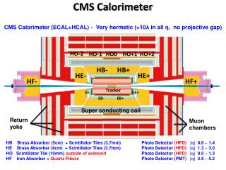
CMS Calorimeter Geometry EB, EE, HB, HE map to 18 RCT crates Provide e/g and jet, t, ET triggers
Current Calorimeter Trigger Algorithms • e/g Rank = Hit+Max Adjacent Tower • Hit: H/E < Small Fraction • Hit: 2 of 5-crystal strips >90% ET in 5x5 Tower (Fine Grain) • Isolated e/g (3x3 Tower) • Quiet neighbors: all 8 towerspass Fine Grain & H/E • One of 4 corners 5 EM ET < Thr. • Jet or t ET • 12x12 trig. tower ET sliding in 4x4 steps w/central 4x4 ET > others • t: isolated narrow energy deposits • Energy spread outside t veto pattern sets veto • t Jetif all 9 4x4 region t vetoes off
CMS Upgrade Trigger Strategy • Constraints • Total output rate of L1 Trigger is 100 kHz • Input rate increases 2-10 times over LHC design (1034 cm-1s-2) • Number of interactions in a crossing (pileup) increases 4-10 times • Thresholds will need to remain about the same to fulfill physics needs • Strategy for Phase 1 Calorimeter Trigger (operating 2016+): • Present L1 algorithms inadequate above 1034 or 1034 w/ 50 ns bunch spacing • Pileup degrades object isolation (electrons and taus) • More sophisticated clustering & isolation needed for busier events • Process with full granularity of calorimeter trigger information • Current FPGAs allow more complexity and flexibility in algos and tuning of isolation and energy cuts • Initial L1 Trigger simulations show a significant rate reduction with upgraded calorimeter trigger
CMS Upgrade Calorimeter Trigger Algorithm Development Particle Cluster Finder Applies tower thresholds to Calorimeter Creates overlapped 2x2 clusters Cluster Overlap Filter Removes overlap between clusters Identifies local maxima Prunes low energy clusters Cluster Isolation and Particle ID Applied to local maxima Calculates isolation deposits around 2x2,2x3 clusters Identifies particles Jet reconstruction Applied on filtered clusters Groups clusters to jets Particle Sorter Sorts particles & outputs the most energetic ones MET,HT,MHT Calculation Calculates Et Sums, Missing Et from clusters HCAL Δη x Δφ=0.087x0.087 η ECAL φ e/γ HCAL η ECAL φ τ HCAL η ECAL φ jet
Cal Trig. Efficiencies & Rates(CMS Upgrade) Taus Isolated Electrons Upgrade Existing Upgrade Existing 4x Reduction in rate at 25 pileup events per crossing & improved efficiency Isolated Electrons Taus Isolated Electrons Upgrade Existing Upgrade Existing
Upgrade Compact Calorimeter Trigger Architecture* 2 - 5 Summary Cards 21 Region Processors x10η, x26φ 21 Input Processors x8η, x24φ Regions Sort e/g & t Build & Sort Jets ECAL Tower Energy (8bit) Info (1bit) HCAL Tower Energy (8bit) Info (1bit) Process Process Process Tower Energy (9bit) Veto (1bit) X8 e/g and t’s x8 Jets Regional results: top e/g’s and t’s, 4x4 tower sums w/ ½ tower res, ECAL ET To Global Trigger Possibility to run different summary cards in parallel to optimise e/g, t, jet or energy sum path. • *Alternative to this pipelined architechture: See talk by G. Iles
Technology Upgrades for the Compact Calorimeter Trigger • A new system begets new hardware • mTCA (AMC standard) • Compact, hot swappable boards • System shrinks, now need only six 7U crates in one rack • Operate new systems in parallel • Optical links instead of copper • Compact, optical ribbon cables for data transmission • Need to align links (data sharing, etc.) • Advanced Monitoring and Configuration • mTCA Controller Hub (MCH) uses TCP/IP protocols • 100Base-X Ethernet over backplane • IPMI for initialization and monitoring • Initialization and Configuration over LAN • FW upgrade and maintenance • Algorithm Flexibility with newer FPGAs • Currently designing for XILINX Virtex-6 • Integrated GTX links for data transmission (up to 6.5 Gbps)
1000Base-X Ethernet Demonstrator • Running lightweight IP (lwIP) TCP/IP stack under Xilkernel • Connected to departmental network • Test #1: iPerf Xmt/Rcv between ML506 and PC: • Rcv: 14 Mbps • Xmt: 12-19 Mbps • Test #2: Echo server between two ML506 bds • Both boards running server and client app Test Board to Connect to µTCA Fabric A GbE Running on SATA Cable Xilinx ML-506 Virtex-5 Evaluation Board
MMC Project • MMC: Module Management Controller • IPMI endpoint for managing cards in µTCA Crates • UW Project: A “ground-up” implementation of an MMC based on an Atmel AVR32-bit Microcontroller • Supports the standard IPMI commands dictated by the specifications, plus additional commands for operations outside the scope of the MMC specification • A full list of commands in backup slides • Communicate with module prior & after FPGA initialization via LAN connection to MCH card in µTCA Crate • Used for: • Power control & monitoring (incl. over-voltage/temp. protection) • FPGA Boot Image Selection & Load Control • Post-boot FPGA Configuration (e.g., geographical card IP address) • Used on multiple CMS electronics upgrade designs
UW MMC Reference Design Hardware Block Diagram (AMC Board) Module Backend Power Temp. Sensor (TMP36) Temp. Sensor (TMP36) FPGA Config Flash ADC Inputs Backend Pwr Enable Config Load Path Primary FPGA Atmel UC3A1512 Microcontroller (512KB Flash, 64KB SRAM) Boot Image IPMB (I2C) Select FPGA Flash Load GA0-GA2 FPGA CPU Reset Augmented SPI (Post boot config path) Console SIO Interface Blue (Non-volatile config settings) 8KB SPI EEPROM LED1 Handle µSwitch LED2 IPMI LEDs
MMC Project: Hardware & Remote Access Prototype Development Platform Sensor display via NATView (Java LAN application for MCHs mfg’d by NAT GmbH) Remote Linux Shell Access via ipmitool
Flash-over-LAN (FoL) Objective: Support remote update of FPGA Flash over the MicroTCA GbE connection FPGA-based server (Microblaze processor) Uses TCP/IP stack (lwIP) running under Xilkernel Common driver API for supporting different Flash implementations (e.g., BPI, SPI) with device-specific drivers PC-based client Connects to server on AMC card to deliver new image (supports MCS and binary file formats for Flash image) Development Platforms: Xilinx ML605 eval board for BPI flash, BU AMC13 for SPI flash Programs ML605 parallel flash about 3x faster than Xilinx iMPACT program
Flash-over-LAN (FoL) Block Diagram Advantages of the FoL Architecture: Primarily C/C++ implementation, as opposed to HDL (more productive development environment) Client model can support additional file types as necessary (e.g., SREC or binary) Common Server can support different device types as necessary via Device-Specific Driver interface Can manage multiple boot images and FPGAs on a single AMC card MCS File Xilinx FPGA (AMC Card) TCP/IP Connection (GbE) FoL Common Server Device- Specific Driver Flash I/O Core FoL Client (PC) FPGA Flash (can be serial or parallel Flash memory)
Data Alignment Study • Absolutely necessary for tower-level data sharing across calo regional boundaries • Problem: Several sources of misalignment • Length of connection, phase and latency variation in SerDes links, and phase variation of clocks between clocks and cards • 4 Test Cards in a custom 2x2 test fabric • Virtex-5 Rocket I/O GTP links • LHC style clock-based timing • Local Trigger Timing and Control (TTC) system for clock generation • Link synchronization test bed • Simulates 2 separate crates of 2 cards each • Goal: demonstrate alignment of 56 separate channels all operating on the same time base
Data Alignment Study: 2x2 Firmware Test Bed Fabric Ch15: Config Channel (Ring) 12 Inter-Card + 2 Intra-Card Loopback X/R channels per board 0 (master) 1 (slave) 40 MHz Clk 4X (Passive) 56 total active channels Ch14: Align Cmd Brdcast 40 MHz 4X “Crate 1” TTCvi “Crate 2” 4X 40 MHz 4X 40 MHz Clk 2 (slave) 3 (slave) 4X
Data Alignment Method • Identify a target latency for each SerDes pair • Set scheduled launch and arrival times for data at all SerDes endpoints per a common global reference, such as the Bunch Crossing 0 signal • Launch/arrival times derived from design • Measure actual latencies by launching special test characters (8b/10b K char) from Tx links at scheduled times • Measure actual arrival times of K chars at Rx links in comparison to expected arrival times from design • Automatically compensate by adding delay at Rx end • Can add delay in fractions of LHC clock, depending on link rate • 4 test cards 56 links at 1.6 Gbps synchronized: • proper alignment was verified using test pipelines to compare expected data (from links) with actual data (generated in the local pipeline).
Cal Trigger Processor Prototype Card Block Diagram Backplane Side Front Panel Side 12-Channel Optical Receiver ECAL Eta Sharing Links Link Clock Conditioning Circuitry SDRAM ECAL 12-Channel Optical Receiver Front End FPGA XC6VHX250T (GTX links) 12x8 Region Processing FPGA XC6VHX250T (GTX links) Phi/Corner Sharing HCAL 12-Channel Optical Receiver HCAL 12-Channel Optical Receiver FPGA Image Flash (Parallel) TTC/DAQ to AMC13 Regional Outputs MMC 12-Channel Optical Transmitter Fabric A GbE (MCH1) Secondary Power Supplies IPMI
SLHC Regional Calorimeter Trigger Backplane Signal Allocation Sharing I/O Slots 2-3 & 10-11 Processor Card Slots 4-9 Fat Pipe (via MCH1 or MCH2) Custom Passive Fabric (CPF) Φ-Sharing Ring
SLHC Upgrade RCT Crate Clock/Control from TTC Crate Output to DAQ Outputs to GCT PM2 Spare Slot Sharing I/O Card Sharing I/O Card Cal Trig Processor Cal Trig Processor Cal Trig Processor BU AMC13* Cal Trig Processor Cal Trig Processor Cal Trig Processor Sharing I/O Card Sharing I/O Card Spare Slot (uTCA form factor, Vadatech VT892 style layout) PM1 MCH Right Sharing Data to neighbor crate (X, R MTP Ribbon) Left Sharing Data to neighbor crate (X, R MTP Ribbon) HCAL/ECAL TPGs from LIP oSLB & Minn. µHTR Cards Ethernet Uplink(s) *See talk in XTCA working group by E. Hazen
Calorimeter Trigger Evolution Present HCAL HTR Cards Existing Copper Cables To DAQ Regional Calorimeter Trigger Via HCAL DCC2 To DAQ Via GCT New Optical Receiver Existing Copper Cables ECAL TCCs To DAQ ECALIndiv. Fibers (LC) Via ECAL DCC Final HCAL uHTR Cards Trigger Primitive Optical Patch Panel Optical Ribbons To DAQ Via BU “AMC13” ECAL Opti. Ribbons SLHC Cal Trigger Processor Cards HCAL Opti. Ribbons To DAQ Optical Ribbons ECAL TCCs Via BU “AMC13” To DAQ New Optical Transmitter Via ECAL DCC Interim
Conclusions and Future Plans • A new CMS Compact Calorimeter Trigger will meet and exceed the needs of the experiment as the luminosity and pileup increase • Flexible, low latency design using modern FPGAs • Ease of maintenance and operation with mTCA standard • Small size allows installation in parallel to validate system with current version • The new tools and techniques to operate the system are falling into place • Flash over LAN, MMC with IPMI, Data Synchronization Technique • Goal is to have demonstrator at the end of 2011 • Expect to remove some of existing calorimeter cables and replace with optics in 2013 • Full system installed by 2016
UW MMC IPMI Command List NetFn Class Color Code Application (06h/07h) Sensor/Event (04h/05h) Storage (0Ah/0Bh) PICMG (2Ch/2Dh) Custom (32h/33h)
Tx Side Alignment Block Diagram Scheduled Delay Launch Delay Counter Data Processing Logic in FPGA Fabric SERDES Tx Port (Dedicated Logic) Ena TC Link Ena Control Global Align Cmd Tx Data Tx Parallel Data MUX Comma Align Char (Locally-Generated Control Characters
Rx Side Alignment Block Diagram Delay Regs SERDES Tx Port (Dedicated Logic) Trigger Rx Data Data Processing Logic in FPGA Fabric Delay Select MUX Rx ParallelData (Dly Src Sel Mux) Yes/No =Align Char? Global Align Cmd Control Fixed Rx Delay Reg Ena TC ACC Arrival Counter Scheduled Arrival Fixed Rx Delay