Download
1 / 26
260 likes | 595 Views
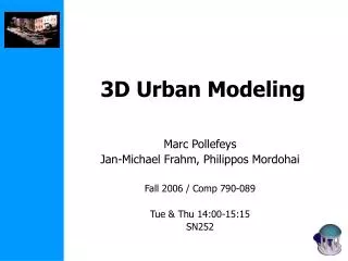
3D Urban Visibility Analysis with Vector GIS Data. SULEIMAN Wassim 1 , JOLIVEAU Thierry 1 , FAVIER Eric 2 1 ISTHME-ISIG CNRS/UMR EVS, Université Jean Monnet - Saint-Etienne. 2 DIPI EA 3719 École Nationale d'Ingénieurs de Saint-Etienne wassim.suleiman@univ-st-etienne.fr

E N D
3D Urban Visibility Analysis with Vector GIS Data SULEIMAN Wassim1, JOLIVEAU Thierry1, FAVIER Eric2 1ISTHME-ISIG CNRS/UMR EVS, Université Jean Monnet - Saint-Etienne. 2DIPI EA 3719 École Nationale d'Ingénieurs de Saint-Etienne wassim.suleiman@univ-st-etienne.fr thierry.joliveau@univ-st-etienne.fr eric.favier@enise.fr 19th annual GIS Research UK (GISRUK)- University of Portsmouth - 27th-29th April 2011
Fields of use : Urban and landscape planning Navigation systems Visual surveillance Measures in view assessment Inter-visibility Isovist and viewshed Global visibility Visibility analysis
Main technique : ray tracing 2D Vector data 2.5D Raster data Brossard & Wieber
3D ? Wii home
Entities ? Public Eye Source : DSS for Coastal Protection Design by Cdr.Phinai Jinchai
One idea : 3D Voxel model Ray tracing (Pyysalo et al. 2009), (Morello & Ratti 2009)
Another idea in vector mode • 3D environment considered as a constellation of polygons • TIN terrain model + • 2D footprints with height extrusion 3D polygon plane facets (terrain, building)
3D Data Model terrain facet building wall roof view point
Data and Tools • Data • Totopographic Database of IGN • Tool • Matlab • Easy of use • Rapid prototyping/debugging of sophisticated code • Tools for GIS data import and export from ArcGIS (Mapping Toolbox) • Tools for simulation and data analysis (Symbolic Math Toolbox, Parallel Computing Toolbox, Statistics Toolbox, Optimization Toolbox) • Easy rapid visualisation • ArcGIS • Interpolation, visualisation
Principle of the computation • If Test1 and Test2 is verified then there is no intervisibility between the two points
Polygone Segment Principle : intervisibility between two points connected by a segment ? • Polygon / Segment intersection in the 3D environment ?
Plan Line Step 1: Find the plan of the polygon and the line of the segment (3D)
Plan Intersection point Line Step 2: Find the Intersection point between the plan and line(3D)
Plan Polygone Intersection point Step 3: Check if the Intersection point belongs to the polygon (2D) (Test1)
Intersection point Line Step 4: Check if the Intersection point belongs to the segment(Test 2) If the results of tests 1 and 2 are true, the segment and the polygon intersect. => the polygon blocks the visibility between the extremities of the segment
Order of complexity of the algorithm • Function of : • the number of the grid points • the number of the polygons in the 3D environment Necessity to reduce the number of the 3D polygon by simplifying the TIN model and Building
Simplifying the DEM • Eliminating extra points in the same level (IsoLevel) within 1 m height interval parameter DEM with IsoLevel simplification DEM
Simplifying the buildings polygon • The extra collinear points were eliminated Simplified building polygon Original building polygon
Results of 3D simplification • The execution time is 2 times faster • Negligible change in the intervisibilty map and viewshed map (less than 5%)
Future work • Vegetation layer • “Real” 3D Isovist • Points on the building facades • More complex buildings models • Implementation in GIS software Decouvrir Arc de triomphe
Thank You Images sources : Woo home : http://www.woohome.com/photograph/steep-hills-of-san-francisco DSS for Coastal Protection Design by Cdr.Phinai Jinchai http://www.dss4cpd.com/dmain/index.php?q=node/26 Public Eye : http://www.globalsecurity.org/eye/html/wtc_noaa_wtc3.htm Decouvrir Arc de triomphe : http://decouvrir-arcdetriomphe.blogspot.com/2011/04/quizz-anecdotes.html