MEP configuration pros/cons
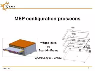
MEP configuration pros/cons. Wedge-locks vs Board-in-Frame updated by D. Pankow. Why the recent reviewer uproar over e-box design & analyses… Several unexpected / unexplained vibration failures (including NuStar @ SSL)

MEP configuration pros/cons
E N D
Presentation Transcript
MEP configuration pros/cons Wedge-locks vs Board-in-Frame updated by D. Pankow
Why the recent reviewer uproar over e-box design & analyses… Several unexpected / unexplained vibration failures (including NuStar @ SSL) Most failures involve large Actels(e.g. CQ352) …0.008”w x 0.006”t leads are very fragile) BACKGROUND (the reviewers commonly accepted reference) “Vibration Analysis for Electronic Equipment, 3rd Ed.” Steinberg (2000) J. Wiley His reference database has never been published or reviewed (and is likely quite dated) Requires box mode >2X highest PWB mode to avoid near resonance coupling Most of this can be predicted (FEM or analytic) from dynamics & published material data The PWB first mode predicts are too conservative (assumes no stiffening by components) COMMONLY USED PACKAGING PWB motherboard with board side Wedge-Loks Wedge-Loks provide 2 PWB fixed edges, backplane & board fronts are 2 PWB pinned edges Individual stacked board frames Frame ledge with screw support only is quite marginal (4 pinned PWB edges) Adding Epoxy edge fillets yields highest board first mode (4 fixed PWB edges ← Best Fn) Stacked board frames provide marginal box shear stiffness MAVEN PC-104 board to board connectors were unreliable, so changed to wired backplane MEP configuration discussion
HISTORICAL REVIEW THEMIS(wedge-loks) – post launch analyses indicate design was adequate Random ASD: 0.04 G2/Hz @ 80-170 Hz → Steinberg: ~100 Hz PWBs → ~200 Hz box RBSP(wedge-loks) – post CDR analyses revealed adequate design (APL reviewed) Random ASD: 0.10 G2/Hz @ 80-800Hz → Steinberg: ~100 Hz PWBs → ~200 Hz box MAVEN(board frames) – significant re-design & evaluation was needed (+ D CDR) Random ASD 0.15 G2/Hz @ 200-800Hz → Steinberg: ~300 Hz; PWBs → ~600 Hz box Mass Ds: (6.62 kg original + 0.97 kg increase)●306 g MDM harness cover 318 g – shear panels ●70 g for 100 box screws ●178 g - DFB stiffener ●100 g - MAG stiffener Recent MAVEN / SSL based advances or “review gains” Finite fatigue life has now been accepted by both APL & GSFC reviewers Assume 4X accumulated vibration exposure with < 25% fatigue damage PWB’s epoxy fillets to board frames to increase board resonant frequency. 50/50 Boron Nitride filled EA-9309 Epoxy for improved thermal conductivity SSL tested epoxy bond strength margin > 12 EM board “tap test” or sine signature now needed for margin verification MEP configuration discussion
DON’T Actel CQ352 package soldered to primary PWB MEP configuration discussion DO same Actel ! in CCGA package on plug-in daughterboard (non flight parts shown) • Flown by GSFC groups – draft CCGA standard released • batch soldered by JPL or a few approved vendors • high 1st mode is not a worry, main PWB rolls off inputs • Non-flight flash parts can be plugged in for development • Success oriented approach • ‘One Shot’ fab – rework unsettling • Rigid ceramic body limits max PCB deflection to ≈0.010”
DON’T PWB’s parallel to panel MEP configuration discussion • SPP parallel PWB: 1.25 G2/Hz • Steinberg calls: no easy solution ! • Likely > 300 Hz all PWB; > 600 Hz box • All PWB’s may need stiffeners • ≈ Mass Cost: 5.94kg now + 1.64 kg added • 7 PWB stiffeners @ 0.18 kg each • Shear panels & screws @ 0.37 kg • SPP perpendicular: 0.04 G2/Hz • Like THEMIS, Easier than RBSP ! • Steinberg calls: > 100 Hz PWB; > 200 Hz box • Wedge-loks or epoxied frames adequate • PWB frames with 8 (corner & side) skewers may be adequate. DO PWB’s perpendicular to panel CAUTION: box Random Test Specs can change
MEP configuration discussion PWB’s SHOULD BE TO BE FLIPPED 90° MAVEN skewer locations Alternate locations for higher stiffness CURRENT MASS VALUES (June 2011)
COLLECTED COMMENTS Reserve a (9th) commonboard center skewer position for PWB stiffening or shield support Large parts should not be located close to the center of a PWB (max deflected curvature) Screwed 1/32” hard anodized aluminum shield boards provide board to board EMI isolation Maven frames were “dead mass” above ≈250 Hz where shear panels were needed NOTE that any one “offending” PWB will drive the whole box design Wired backplane can be used with Wedge-Lok concept (include F/R card edge supports) MEP configuration discussion
Wedge Lock Approach • Wedge Lock design features • Boards have side entry into stack, secured by wedge locks • Uses a backplane for board interconnect • Pros • Fatigue lifetime analysis indicates that wedge locks provide stiffer boards (see chart next slide) to support large, flat pack ICs, at lower overall mass • The lower mass assertion needs some backup • Backplane is a really convenient method of board interconnect • Board integration (and de-integration) is simpler • Cons • Close tolerances are required to secure boards, and make backplane connector engage. Usually involves special assembly techniques, shims, etc. • Backplane connector interface is subject to large, lateral mechanical loads • Electrical shielding between boards, for radiated interference, is more difficult. This is especially true at high frequencies, and SPP requires HFR reception up to 20MHz. • Heat conduction is really only available via wedge locks, i.e. on two sides of board • Some team members simply don’t want this approach.
Board margin requirements • Pankow worked some general SPP cases • Board 6.3” x 9.3” x .062” thick • Same Actel (CQ352) and similar position seen on MAVEN DFB board for reference • Design life = 4X expected test durations + launch
Board-in-Frame Approach • Board-in-Frame design features • Boards are stacked, held together by skewers, can be either horizontal or vertical stack. • Uses external harnesses for board interconnect • Pros • Each board is in its own EMI-tight enclosure • That’s not to say we won’t have noise problems! It’s just one step in improving noise immunity. • Better thermal conduction, four sides available for heat transfer • On MAVEN, I think epoxy was required to make heat transfer really work well, and was needed to get board frequency up to desired level • Cons • Potential for differential motion between slices, fretting damage on frames • Harder to achieve required box stiffness, box frequency >2X board frequency • MAVEN required external stiffeners, which added mass
Board-in-Pan Approach • Board-in-Pan (5 sided box) design features • Boards are stacked, held together by cornerskewers, can be either horizontal or vertical stack but horizontal is nicer. • Uses external harnesses for board interconnect • UMN approach to LNPS slice • Base/bottom of horizontal stack • Pros • Each board is in its own EMI-tight enclosure • That’s not to say we won’t have noise problems! It’s just one step in improving noise immunity. • Board can have one or more center post(s) • Better thermal conduction, four sides + posts available for heat transfer • On MAVEN, I think epoxy was required to make heat transfer really work well (more screws?), and was needed to get board frequency up to desired level • Cons • Potential mass hit if floor is thick enough to be structural • Potential for differential motion between slices, fretting damage on frames • Not with UMN’s nice V-grooves! • Harder to achieve required box stiffness, box frequency >2X board frequency • MAVEN required external stiffeners, which added mass