Download
1 / 7
70 likes | 87 Views
This document discusses the VME interface for ECAL readout hardware, including the VME chip, serial command system, and address map. It also highlights what has been implemented and what could potentially be implemented in the future.

E N D
Calice ECAL Readout Hardware VME Interface Edward Freeman ECAL Meeting 23 Oct 2003 Rutherford Appleton Laboratory
VME FPGA Top level VME_interface VME_serialiser VME_Slink Mux management Edward Freeman Rutherford Appleton Laboratory
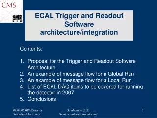
VME Chip The VME chip is made up of four main parts • 1) The VME interface • Converts from asynchronous the VME bus to a simple synchronous bus. • 2) Serialiser • Bridges the simple synchronous bus to a serial stream to control the BE and all FE chips. • 3) Slink to VME bridge • Connects Slink read out data to the VME interface. • 4) Management block • Deals with clock selection, revision No., status reg, etc. Edward Freeman Rutherford Appleton Laboratory
What’s implemented and what's not The interface is designed to work in a VME64x back-panel but does not implement all of the 64x functions at this time. • 32bit data and 32bit address. (32bit aligned only) • Geographic addressing. (but not CR/CSR) • 32bit block transfer. Things that aren't implemented, but could be: - • CR/CSR and the full “Plug and play” configuration. • Interrupts. • Other data and address sizes. (i.e. 8bit, 16bit, 24bit, 64bit) Edward Freeman Rutherford Appleton Laboratory
Address map for VME interface This is out of date as the RAM serial commands needs to be a minimum of 4KB for CMS Edward Freeman Rutherford Appleton Laboratory
Serial command system The serial command system is designed to be small and not affect timing in CMS’s complex FE chip. As a result of this it isn't the simplest interface to control and some of the complexity has been pushed into the software. The software is responsible for assembling the serial command, putting it into the read or write register respectively and then triggering it by writing the length of command to a third register. There is a slave interface in both VHDL and Verilog, it is tested and ready for use. This should be relatively easy to drop into other designs. There is a full description of the serial command system at: - http://www.te.rl.ac.uk/local/ESDG/SDG/Projects/cms-fed/qa/external/firmware/fe-fpga/docs/fed_fe_fpga.pdf Edward Freeman Rutherford Appleton Laboratory
THE END Edward Freeman Rutherford Appleton Laboratory