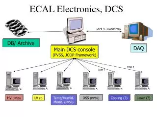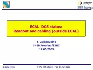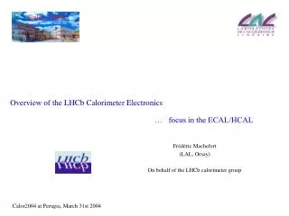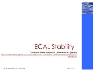
ECAL electronics
Guido Haefeli, Lausanne PEBS meeting 10.Jan. 2011. ECAL electronics. Overview. SPIROCA in testbeam 9.2010 (Jean- Baptiste ) Why change from SPIROCA to VATA64? VATA64 measurements Plans for the electronics for testbeam in 2011 . Output dependence on the rate.

ECAL electronics
E N D
Presentation Transcript
Guido Haefeli, Lausanne PEBS meeting 10.Jan. 2011 ECAL electronics
Overview • SPIROCA in testbeam 9.2010 (Jean-Baptiste) • Why change from SPIROCA to VATA64? • VATA64 measurements • Plans for the electronics for testbeam in 2011
Output dependence on the rate A SiPM is illuminated with stable light pulses produced by a LED (Light pulses are monitored with a PMT)
Baseline shift (fluctuation) Pedestal spectra Without common mode correction After common mode correction
SpirocA card problem causing oscillation • The shaping time settings (175ns) make the chip to oscillate, maybe also other settings have a negative effect on the stability. • The settings were crosschecked with the Aachen electronics and are correct. • Same chip module as on Aachen board used. no hint where the problem is.
SpirocA • With the use of the high and low gain output on the two sides, 4 measurements for each event are taken. • Why are high and low gain measurement required? Noise in high gain mode is too large for small signal measurement! • Difficult to calibrate • Large baseline fluctuation for large signal. • In the ECAL for large energy showers, order of 9 channels receive large signal, this gives large baseline fluctuations. • Difficult to remove this on the flight! • Output dependent on the injection frequency • No or very limited single photon detection possible with the ECAL detector, would be nice for calibration.
VATA64 • Very low noise, with one gain the range of 0..100pC can be covered. (see slide on dynamic range) Therefore only two measurements need to be calibrated! Noise below one photon. Resolution restricted by the 12-bit ADC. • No baseline fluctuation for large signals can be observed. Injection of 8 channels with large signal leaves rms of neighbours unchanged. • Single photon detection possible in high gain mode, this is useful for calibration. • Power consumption, some power saved by less drivers (only one gain output) and only half the number of cards. Reduction to current ECAL budget possible.
Power consumption measurement • SPIROCA • Pch=13mW, Pcard=428mW, PECAL=51W (120 cards) ( • A large fraction not used by the SPIROC but by the other components. • High and low gain readout consumes power also in the ADC board (doubles the number of channels). • VATA64 • Pch=23mW, Pcard=1.5W, PECAL=75W (50 cards) • Power saving options (shutting down fast shaper has to be implemented first) • Remove additional amp for debugging, power measured on the total card (~10mW/CH for the VA chip only)
Dynamic range • Required dynamic range for the ECAL is 0..2000 photons. The number of effective pixels is below 2000, the detectable range should include some margin. • With the nominal gain (0.26Me/PE) this converts in a dynamic range of 0..83pC. • Since the VATA64 offers a dynamic range of 0..50pC a external current divider must be placed to reduce the signal by a factor 2. • The external current divider has only a very small or no impact on the noise and the dynamic range can be extended to 0…100pC. This will be implemented on the next version electronics.
Baseline change with 8 pulsed channels Neighbouring channel Rms=0.75 ADC
Measurement with high gain and low gain High gain 8 ADC/PE Low gain 4 ADC/PE
Measurement with high gain and low gain High gain 8 ADC/PE Measurement with detector as used by the tracker (50umx50um)
Shaping time settings 50ns to 300ns Fastest setting is 50ns which corresponds to a peaking time of the slow shaper Tps=200ns Time of maximum measured after the arrival of the input signal (green in the plots) Tp=150ns Tps=300ns Tp=50ns Tps=200ns Tp=100ns Tps=250ns Tp=300ns Tps=450ns
Testbeam 9.2011 • Use VATA64 v2, the chips are available now. The v2 was tested in the lab. • Use intermediate PCB for connection of the SiPMs with the PCB. • Separate electronics card with the possibility to read 3x21 channels on the 64 channel readout chip. • Card to card connection with small stacking height connectors. Has the advantage that different chips can be used to read the detectors without removing the connections to the SiPMs.
Testbeam 9.2011 Should we also provide a new version of the SPIROC readout? Card could be plugged instead of the VATA64.
Conclusion • We still need to find the shaping time bug on the SpirocA card • We need to decide if we produce a new version SpirocA card for the next testbeam • The VATA64 chip has clearly advantages over the SpirocAso we want to use it in the next testbeam