Download
1 / 53
530 likes | 537 Views
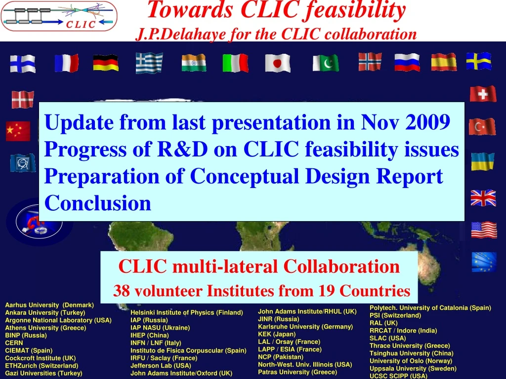
Towards CLIC feasibility J.P.Delahaye for the CLIC collaboration. Update from last presentation in Nov 2009 Progress of R&D on CLIC feasibility issues Preparation of Conceptual Design Report Conclusion. CLIC multi-lateral Collaboration 38 volunteer Institutes from 19 Countries.

E N D
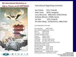
Towards CLIC feasibility J.P.Delahaye for the CLIC collaboration Update from last presentation in Nov 2009 Progress of R&D on CLIC feasibility issues Preparation of Conceptual Design Report Conclusion CLIC multi-lateral Collaboration 38 volunteer Institutes from 19 Countries Aarhus University (Denmark) Ankara University (Turkey) Argonne National Laboratory (USA) Athens University (Greece) BINP (Russia) CERN CIEMAT (Spain) Cockcroft Institute (UK) ETHZurich (Switzerland) Gazi Universities (Turkey) Polytech. University of Catalonia (Spain) PSI (Switzerland) RAL (UK) RRCAT / Indore (India) SLAC (USA) Thrace University (Greece) Tsinghua University (China) University of Oslo (Norway) Uppsala University (Sweden) UCSC SCIPP (USA) John Adams Institute/RHUL (UK) JINR (Russia) Karlsruhe University (Germany) KEK (Japan) LAL / Orsay (France) LAPP / ESIA (France) NCP (Pakistan) North-West. Univ. Illinois (USA) Patras University (Greece) Helsinki Institute of Physics (Finland) IAP (Russia) IAP NASU (Ukraine) IHEP (China) INFN / LNF (Italy) Instituto de Fisica Corpuscular (Spain) IRFU / Saclay (France) Jefferson Lab (USA) John Adams Institute/Oxford (UK)
4 Additional Members • ETHZ/ Switzerland: • Alignment R&D • IHEP/China: • X-band RF components developments (design and construction) • JAI (Oxford)/UK: • Beam instrumentation and diagnostics • UCSC-SCIPP/USA: • LC detector R&D
THE COMPACT LINEARCOLLIDER (CLIC) STUDY • Objective:site independent study exploring possible extension of e+/e- linear colliders into the Multi-TeV colliding beam energy range by developing most appropriate technology : • ECM energy range complementary to LHC =>ECM = 0.5- 3 TeV • L > few 1034 cm-2with acceptable background & energy spread • Affordable cost and power consumption • Physics motivation: • Consensus supported by ICFA of Lepton Collider (precision) favored facility to complement the LHC (discovery) in future • "Physics at the CLIC Multi-TeV Linear Collider: • http://clicphysics.web.cern.ch/CLICphysics/ • Present goals: • R&D addressing Feasibility Issues • Conceptual Design (Accelerator & Detector) with preliminary performance & cost estimations http://clic-study.web.cern.ch/CLIC-Study
10 CLIC Feasibility Issues Two Beam Acceleration: Drive beam generation Beam Driven RF power generation Two Beam Module RF Structures: Accelerating Structures (CAS) Power Production Structures (PETS) Ultra low beam emittance and beam sizes Emittance generation & preservation during acceleration and focusing Alignment and stabilisation Detector Adaptation to short interval between bunches Adaptation to large background at high beam collision energy Operation and Machine Protection System (MPS)
Addressing all major CLIC technology key issues in CLIC Test Facility (CTF3) Demonstrate Drive Beam generation(fully loaded acceleration, beam intensity and bunch frequency multiplication x8) Demonstrate RF Power Production and test Power Structures Demonstrate Two Beam Acceleration and test Accelerating Structures PULSE COMPRESSION FREQUENCY MULTIPLICATION magnetic chicane 150 MeV e-linac 30 GHz test stand 3.5 A - 1.4 ms Delay Loop Combiner Ring CLEX (CLIC Experimental Area) TWO BEAM TEST STAND PROBE BEAM Test Beam Line 28 A - 140 ns Photo injector tests, laser Infrastructure from LEP total length about 140 m
CTF3 completed, operating 10 months/year, under commissioning:Drive Beam Generation demonstrated RF pulse at structure input 1.5 µs beam pulse RF pulse at output 10 m Fully loaded acceleration RF to beam transfer: 95.3 % measured 7 A @ 3 GHz DELAY LOOP Beam intensity multiplication * 8 Beam frequency multiplication * 8 COMBINERRING 4 A – 1.2 ms 120 Mev @ 1.5 GHz 28 A @ 12 GHz DRIVE BEAM LINAC CLEX CLIC Experimental Area
CTF3/CLEX (CLIC Experimental Area) Test beam line (TBL) to study RF power production (1.5 TW at 12 GHz) and drive beam decelerator dynamics, stability & losses - Two Beam Test Stand to study probe beam acceleration with high fields at high frequency and the feasibility ofTwo Beam modules Test Beam Line TBL Two Beam Test Stand Probe Beam Drive and probe beams in CLEX from June 2008 Installation completed except for PETS in TBL
Progress on tests of Accelerating Structures equipped with Damping Slots 3 structuresno damping: Exceeded 100 MV/m at nominal breakdown rate 2 structureswith damping slots: Exceeded 100 MV/m at larger breakdown rate Low statistics, high reprod. 25% reduction of perform. by Damping Slot Effect attributed to excessive RF pulse heating Nominal structure (TD24) with reduced RF pulse heating under tests with damping without damping CLIC goal: 100 MV/m loaded with BR<3 10-7/m
Fields and RF pulse heating along the Accelerating Structure Without Damping With Damping Es Ea Prf DT High DT : 47 degC whereas T18 is only 12.5 degC
Breakdown rate versusRF pulsed heating + 35 ºC X 100
RF pulse heating mitigation in nominal CLIC accelerating structure (TD24) Surface magnetic field after RF design optimisation Without Damping With Damping 17%
CERN/CLIC X-band Test-Stand(Under Construction) CERN - CEA – PSI – SLAC Directional coupler Circular pumping port Klystron XL5 Mode convertors RF Valve High voltage modulator Circular waveguide F=50 mm SLED Pulse compressor
Stand alone Test Stand in CTFII Circular WG WG valve Mode converter load pump coupler 0.5 m Pump Tee F-Cup+Isolator ACC 0.5 m girder girder girder Concrete block
Schedule (05/2010) • Klystron and Modulator scheduled to arrive at CERN! • RF components and network require new strategy and more efforts! • 12 GHz power (without compression) available in July 2010!
Applications of X band accelerating structures:CArbon BOoster Therapy in Oncology (TERA)PSI/X-FEL, ELETTRA, SLAC Linac based X-FEL TERA 12 or 5.7 GHz NC Linac (power efficiency) 20
X-band Linac Driven Compact X-ray FEL Courtesy C.Adolphsen/SLAC Linac-1 250 MeV Linac-2 2.5 GeV Linac-3 6 GeV X BC1 BC2 X S Undulator L = 40 m X undulator rf gun LCLS-like injector L ~ 50 m 250 pC, gex,y 0.4 mm X-band main linac+BC2 G ~ 70 MV/m, L ~ 150 m • Use LCLS injector beam distribution and H60 structure (a/l=0.18) after BC1 • LiTrack simulates longitudinal dynamics with wake and obtains 3 kA “uniform” distribution • Similar results for T53 structure (a/l=0.13) with 200 pC charge
PSI-XFEL X-BAND STRUCTURE WITZENMANN FLEXIBLE HOSE VACUUM FLANGES WFM CELLS ( 36-45, 63-72 ) LEGRIS CONNECTOR COOLING BLOCK FEEDTHROUGH 11.994 GHZ, 73 cells, non-damped, sealed, disks Ø65mm, push-pull tuning
Power Production Structure (PETS ) design, built @ CERN, power tests @ CTF3, SLAC Klystron driven @ SLAC CLIC target Drive beam driven @ CTF3 266 ns (240 ns CLIC target) CLIC target CLIC target CLIC target CLIC target
PETS ON/OFF CONCEPT WITH EXTERNAL COMMUTATION AND INTERNAL RECIRCULATION PETS OFF Ramped pulse for beam loading compensation. 0.25 Tunable reflector PETS ON PETS power ON OFF PETS power Recirculation in anti-phase 0.25 Time [s]
PETS COUPLER MINI-TANK DAMPING BAR FIXATION PETS OCTANT SiC BAR PETS mockup for test module in the lab PETS octants assembly S1=212838.222 mm2 • CU-OFE octal prism with slots • The internal surface area calculation was done with CATIA Engineering optimizer module. S2=209235.153 mm2 PETS with damping material
PETS ON-OFF MECHANISM TO ACC. STRUCTURE REFLECTOR COMPACT COUPLER ACTUATOR PISTON COOLING CHANNEL OUTLET COOLING INLET Assembly of PETS “On-Off” mechanism combined with compact coupler
PETS • Structure (8 octants) with “compact” couplers, Vacuum “Mini-tank”, “On-off” mechanism ( t «off» 20 ms ) • Cooling circuits (size for 0.5% beam loss, couplers water-cooled, bars cooled by conduction) VACUUM MINI-TANK COMPACT COUPLER WITH ON-OFF MECHANISM VACUUM MANIFOLD PETS OCTANTS PETS for CLIC • PETS prototype is currently under production by CIEMAT. (EUCARD WP9.2)
Two Beam Test Stand (TBTS) in CTF3/CLEX All hardware installed! Beam in both lines up to end ! Commissioning with beam: PETS 2009, Two Beam Acceleration 2010
Test Beam Line (TBL) • High energy-spread beam transport • decelerate to 60 % beam energy • Drive Beam stability • Stability of RF power extraction • total power in 16 PETS: 1.5 GW • Alignment procedures PETS design 5 MV/m deceleration (35 A) 135 MV output Power 2 standard cells, 16 total
Two Beam Module tests in CTF3/CLEX Test module representing all module types & integrating all various components: RF structures, quadrupoles, instrumentation, alignment, stabilization, vacuum, etc Tests without beam in 2010-11, with beam in CTF3/CLEX in 2012-13 G. Riddone 31
Fire in CTF3 Klystron Gallery (04/03/10) Cleaning overall gallery six months delay….. Pulse Forming Network after fire Pulse Forming Network in Faraday Cage Modulator in Gallery Faraday Cage MDK13 13 = bad luck?
CTF3 Klystron gallery during cleaning of corrosive products
Cleaning procedure Components from each rack dismounted and identified Dust removal from sub components Chemical cleaning Ovens for drying after chemical cleaning Cleaned components waiting for reinstallation in gallery Vacuum ovens for 2nd stage
Damaged cables • >300 cables and ~40 HV vacuum cables in front of PFN damaged • All cables will be repaired – 4 ½ weeks estimated => until 26 May • complete replacement (vacuum) • replace damaged section with connectors at both ends • consequence: • all power still disconnected in the klystron gallery => until 20 May • vacuum pumps off in Delay Loop, Combiner Ring + part of linac • Main worry: testing of connections (plus cleaned electronic racks…) => bumpy start-up?
Updated CTF3 Schedule (six months delay) Optics improvements (DL dispersion) Full transport to CLEX Bunch length control (first tests) TBTS initial PETS tests CALIFES setup new setup when MKS13 available? 1 PETS conditioned to nominal power/pulse lengthTBL PETS tests 2 • Two-Beam test • power & energy gain, 100MV/m Accelerating structure conditioned to nominal power/pulse length 3 PETS breakdown rate measurements??? • TBL studies(limited) 4 1 3 2 • Beam Loading compensation experiment • Measurement of breakdown kicks 5 3 2 1 • Measurement of effect of beam loading on breakdown rate 6 4 5 6 Test of new PETS on-off scheme 7 • TBL studies 30% deceleration ? • Stability studies & improvements • PETS no recirculation • Phase stability • Operation at 5 Hz (or more) • Control of beam losses • Coherent Diffraction Radiation … 8 6 • 1st TBL PETS installationPHIN possible • <--------> 4 5 • 2nd TBL PETS installation • 6 weeks PHIN • phase-coding • Laser preparation 7 8 7 8
Beam driven RF Power Generation Feasibility • RF power generation by single PETS feasibility demonstrated except for breakdown rate. • ON/OFF mechanism being built, still to be tested • Efficient RF power extraction in multiple stages being addressed in TBL under construction for tests with beam • Tests delayed to 2011 by CTF3 modulator fire
Beam collision energy (E) adjustement by accelerating gradient (G) tuning Charge per bunch Q proportional to gradient G for beam stability G= G0*E/E0 → Q = Q0*G/G0 → Luminosity reduction → Better energy spectrum
Luminosity recovery by beam pulse lengthening and repetition frequency
Conceptual Design ReportContribution/Authors by CLIC collaboratorshttps://edms.cern.ch/nav/CERN-0000060014/AB-003131 3 volumes: similar to ILC CDR: Vol1: Executive Summary Vol2: The CLIC accelerator and site facilities Vol3: The CLIC physics and detectors including detailed value Estimate (specific contribution in vol. 2&3, summary in vol. 1) Editorial Board for Volume 2: H.Schmickler (chair), N.Phinney/SLAC, N.Toge/KEK, Outline defined and contributors contacted http://indico.cern.ch/getFile.py/access?contribId=3&resId=0&materialId=0&confId=91998 Vol 3 under responsibility of LCD project (L.Linssen)
CDR schedule Executive Summary Accelerator Detector
CLIC Updated Schedule CLIC CDR and CLIC TDP proposal @ CERN Council European Strategy for Particle Physics @ CERN Council Conceptual Design Report (CDR) Technical Design Report (TDR) ? Project submission?
Extremely fruitful CLIC /ILC Collaboration ILC for a TeV LC based on SC RF technology & CLIC extending LC into Multi-TeV range complementary. Common working groups on technicalsubjects with strong synergy between CLIC & ILC making the best use of the available resources developing common knowledge of both designs and technologies on status, advantages, issues and prospects preparing together by the Linear Collider Community made up of CLIC & ILC experts: proposal(s) best adapted to the future HEP requirements Joint CLIC & ILC workshop (October 18-22 @ CERN) (IWLC10: Linear Collider Accelerator and Detectors)
Conclusion Novel CLIC technology to extend Linear Colliders into the Multi-TeV beam colliding energy range with promising performances and challenging parameters R&D on feasibility issues and concept of 3 TeV multi-TeV Linear collider in a Conceptual Design Report (CDR) by mid 2011 Ambitious Test Facilities: CTF3, ATF1,2, CESR-TA… Exploration to determine LC capabilities & limitations in multi-TeV range Technical design phase (five to six years): engineering design optimization, technological risks & costmitigation Linear collider energy, luminosity and appropriate technology to be defined as the best trade-off following: Physics requirements when better known from LHC/Tevatron results Design performances, technology risk, power consumption and cost Warm thanks to outstanding contributions of CLIC collaboration in the past, present and …. future Close CLIC / ILC collaboration extremely beneficial for Linear Colliders in preparation for best possible future HEP facility as requested by Physics and complementary to LHC
CLIC main parameters http://cdsweb.cern.ch/record/1132079?ln=frhttp://clic-meeting.web.cern.ch/clic-meeting/clictable2007.html
Relative cost of Linear Colliders Reduced CLIC cost/GeV due to - reduced tunnel length (by 4) - reduced equipment per meter of tunnel Additional CLIC offset due to drive beam injectors
CLIC performances (FoM) and cost (relative) as a function of the accelerating gradient Ecms = 3 TeV L(1%) = 2.0 1034 cm-2s-1 Cost Figure of Merit Performance Previous Previous Optimum New New • Performances increasing with lower accelerating gradient (mainly due to higher efficiency) • Flat cost variation in 100 to 130 MV/m with a minimum around 120 MV/m
CLIC performances (FoM) and cost optimisationas function of RF frequency Ecms = 3 TeV L(1%) = 2.0 1034 cm-2s-1 Performance Cost New Optimum Previous Optimum New Previous • Maximum Performance around 14 GHz • Flat cost variation in 12 to 16 GHz frequency range with a minimum around 14 GHz