Low Voltage Technology
390 likes | 583 Views
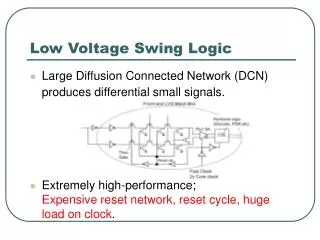
Low Voltage Technology. Pulse Generator Technology Lead Technology. Pulse Generator. 1958, 8 October. Identity ADx XL DR. Feed Through. Defib. protection. Capacitors. Sensor. Crystal. Telemetry Coil. X-ray marker. Golden Thread Welded Bonds. All bonding is doubled for safety reasons.

Low Voltage Technology
E N D
Presentation Transcript
Low VoltageTechnology Pulse Generator Technology Lead Technology
Feed Through Defib. protection Capacitors Sensor Crystal Telemetry Coil X-ray marker
Golden Thread Welded Bonds All bonding is doubled for safety reasons
Magnet Rate <99/min: (and normal energy consumption) 6 months F-U interval 98.6 BOL Magnet Rate ~93/min: (and normal energy consumption) Replacement within 3 months ERI 86.3 Magnet Rate <85/min: Immediate replacement Elective Replacement Indicator Magnet test rate 100 85 EOL EOJ
Stimulationrate 63.2 64.5 65.9 67.4 69.0 70.6 Battery impedance kOhms 10 20 30 40 BOL EOL Elective Replacement Indicator
25 20 15 Stimulation current consumption 10 5 Exemple of current drain Single-chamber unit, rate 60min-1 and 500Ω lead imp. Current drain µA Intrinsic current consumption 0,5ms 1,0ms 0,5ms 1,0ms 0,5ms 1,0ms 1,0 Volt 2,5 Volt 7,5 Volt
How to ”find” the set screw Silicone rubber sealing membrane
VS 1 IS-1 IS-1 VS 1B Cordis 3.2 mm IS-1 Different 3.2 mm ”Short Bore” Connectors
VS 1A / IS-1 VS 1B / IS-1 IS-1 IS-1 VS 1B Cordis 3.2 mm Different 3.2 mm ”Long Bore” Connectors
VS 1B / IS -1 IS-1 IS-1 † Not µ-size cans * Not M/S version Connectors in our Products Sensolog* Dialog* Sensorithm* Regency* Paragon* Synchrony* Trilogy* Affinity* Entity Integrity† Identity† ADx Family†* Microny Integrity µ-size Identity µ-size ADx Family µ-size
M, 5 mm S, 6 mm K, 3.2 mm (IS-1) T, 3.2 mm (IS-1) C, 3.2 mm inline (VDD) (for old version AddVent, obsolete now) Bifurcated 3.2 mm (VDD) Connectors
Lead position Endocardial Myocardial Epicardial
Polarity configuration Bi-polar Uni-polar
Advantages - Bi-polar Less risk of myopotential oversensing Less risk of musclestim. Less risk of Crosstalk and Far Field Sensing Uni-polar or bi-polar leads? • Advantages - Uni-polar • Smaller diameter • Larger “spikes” on ECG ( ) With a bipolar lead, you can program the device to e.g. stimulate unipolar but sense bipolar
Far-field sensing Sensing intrinsic activity in the other chamber Crosstalk Sensing pacemaker- activity in the other chamber
IS-1 connector Bi-polar Uni-polar
Fixation methods Passive Active
J-shaped lead (1421T)
This fractal coating creates a microscopic area ~4-600 times larger than the macro-scopic area (~15 cm2 vs 3,2 mm2 (Isoflex)) Titanium nitride (TiN) coating
Factors affecting threshold Insulation defects/Conductor failure Lead position Inflammatory reaction Scar tissue Polarisation losses
Insulation defect Conductor failure Lead defects
I II III V IV What is stimulated? What is sensed? Reaction to sensing MultisitePacing Rate Modulation 0=NoneR=Rate Modulation 0=None A=AtriumV=VentricleD=Dual (A+V) 0=None A=AtriumV=VentricleD=Dual (A+V) 0=NoneT=TriggeredI=InhibitedD=Dual (T+I) 0=None A=AtriumV=VentricleD=Dual (A+V) S=Single (A or V) S=Single (A or V) NASPE/BPEG Generic Pacemaker Code The Revised NASPE/BPEG Generic Code for Antibradycardia, Adaptive-Rate, and Multisite Pacing, PACE , Volume 25, No. 2, February 2002