Download

1 / 25
260 likes | 560 Views
Low Voltage Low Power Dram. Robert Mills. Presentation for: High Speed and Low Power VLSI design course Instructor: Prof. M. Shams. Introduction. Rapidly growing area of Power Aware systems DRAM Design Evolution Goal: Identify Power Sources in Drams Present Design Solutions

E N D
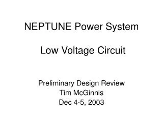
Low Voltage Low Power Dram Robert Mills Presentation for: High Speed and Low Power VLSI design course Instructor: Prof. M. Shams
Introduction • Rapidly growing area of Power Aware systems • DRAM Design Evolution • Goal: Identify Power Sources in Drams • Present Design Solutions • Examine Ultra Low Power issues (Future Concerns) • Proposed Project Plan and Schedule
DRAM Evolution • Market object: Minimize cost / bit stored • 1973 4Kb, NMOS, 1T1C Cell, 460mW, 300ns • 1986 1Mb, CMOS, Boosted circuits, Vdd / 2 bit line reference, 200mW, 100ns • 1996 64Mb, Cell over bit line, 512 cells per column, 180mW, 60ns • 2001 4Gb, Twisted Open Bit line, 270mW, trc= 70ns
1T 1C Dram Cell Data or Column line Potential = Vcc for logic 1 and gnd For logic 0. Q = Vcc/2 C logic 1 Vdd / 2 Q = -Vcc/2 C logic 0 Word or Row Line
WL2 WL0 WL1 WL3 D1 D1* D0 D0* Simple Array Scheme
600 nmos 400 cmos Power (mW) 200 4K 64K 1M 16M 256M 256K 4M 64M 16K Trend in Power Dissipation of DRAMS Memory Capacity (bits)
RAM Chip M Row DE ARRAY Periphery Circuits N Column DE
Unified Power Active Equation • P = Vdd Idd • Idd = miact + m(n-1)ihold + (n+m)Cde Vint F + Cpt Vint F + Idcp • At high frequency ac current dominates • Idd Increases with increasing m x n array size
Destructive Read out • On Readout Data line Charged and Discharged • Idd = (mCDDV + Cpt Vint )F • Reduce Active Power: • Reduce charging cap • Lower Vint and Vext • Reduce Static current
Data Retention Power sources • The Refresh Operation reads data of m cells on the nth word line • An Idd flows each time m cells are refreshed • Frequency refresh current is n / tref
Low Power Dram Circuits • Charge Capacitance Reduction by partial activation of Multi-divided data line. • Increase in memory cells directly increases the CD • Divide one data line into several sections & activate only one sub-section.
Multi-divided data-line & Word Line Y SA A2 A3 SA A4 X Decoder Y A5 SA A6 A7 SA Shared Y-decoder, X-decoder and Sense Amp
Reduction in CDT & QDT • Employing Partial Activation + • Multi divided data line and Word lines • For 256Mb DRAM design Cdt expected drop from 3000 pf to 100pf. • Charge Reduction on Qdt from 3100 pC to 102 pC for experimental 256 Mb DRAM
Operating Voltage Reduction • Reduction in Vdd helps reduces Decoder and Perpheral logic power. • CMOS vs nMOS decoders • Half Vdd data-line pre charge lower power in memory array • CMOS circuit - P = 0.46 : A = 0.7 • NMOS circuit - P = 1 : A = 1
fa fr fp D fr fa fp Vdd/2 0 D Half Vdd Pre - charging Scheme
DC Current Reduction • Column signal path circuitry main source of static current. • DC current flows from the I/O line load to the data lines while column is switched on. • Use Address Transition Detection (ATD) circuitry to activate column switch and main amplifier.
Data Reduction Power Retention • Use Voltage conversion circuits • Use Refresh Time extension • Refresh Charge Reduction
1980 DE 500 Array 24.2W Periphery 640 25.4 W Low C ( CMOS NAND Dec, Part. Act. M-D Data.Line.) 1990 48 168 88 304mW Low Idc ( CMOS Cir, ATD) Low V 5 -> 3.3v Low C ( part. Act. M-D WL) 1994 47mW Low V 3.3 -> 1.5v Low Power circuit Advancement64Mb DRAM (110ns cycle)
Ultra Low Power Concerns • Vt Scaling is major concern for achieving ultra-low voltage power VLSI’s. • DC chip current due to sub threshold current Idc increases exponentially with Vt reduction when Vdd is lowered. • This problem affects data retention current as well as active current.
Trends in Active Current for DRAMS 10 1 Iact 10e-1 Current (A) Iac 10e-2 Idc 10e-3 Capacity 256M 1G 4G 16G 64G Vdd 2v 1.5v 1.2v 1v 0.8v Vt 0.32v 0.24v 0.19v 0.16v 0.13v
Retention Problem • In a Cell, sub-threshold leakage current flow from the capacitor to the data line. • This degrades the data retention time • Drams cells require highest Vt WL DL 1 0 Cs
Two Reduction schemes • The dynamic Vt scheme • In active mode Vt is set low. In stand-by mode the Vt is raised • The Static Vt scheme • Categorized as power-switch and multi Vt scheme.
Conclusion • Source for power dissipation in Drams have been examined • Architectures and Circuits have been reviewed to address these power hungry area. • Future Dram designer need to address Increasing sub-threshold current as Idc >> Iac.
Project Plan & Schedule • Design an Address Decoder and Optimize for low power DRAM application. • Define design problem: 1st – 7th April • Optimize & design Decoder: 8 -15th April • Simulate both designs: 16-22th April • Present Results week of 23rd April • Submit in report on 5th May
References • “Fast Low Power Decoders for Rams”, M. Horowitz, IEEE JSSC, Vol,36, No.10, Oct 2001 • “Low Voltage Memories for Power-Aware Systems”,Itoh, ISLPED ’02, August 12-14, 2002, Monterey, California, USA. • “A 4Gb DDR SDRAM with Gain controlled Pre-Sensing and Ref. Bitline Calibration Schemes in the twisted Open Bitline Architecture”, H. Yoon et al., IEEE, ISSCC-2001 Session 24/DRAM/24.1, Feb. 2001 • “Limitations and Challenges of Multigigabit DRAM Chip Design”, Itoh, IEEE JSSC, Vol. 32, No. 5, May 1997. • “Trends in Low Power RAM Circuit Technologies”, Itoh et al, Proceedings of the IEEE, Vol. 83, No.4 April 1995.