Download
1 / 31
310 likes | 452 Views
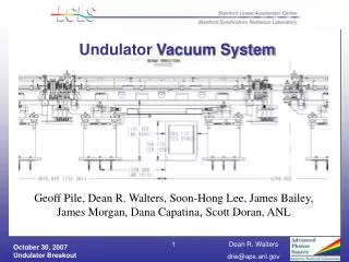
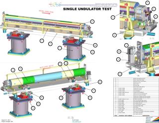
Undulator Commissioning. Heinz-Dieter Nuhn – LCLS Undulator Group Leader June 8, 2009. 29 Undulators Installed. Segment Installation Schedule. Undulator Segments are being installed in the tunnel as they finish tuning 1/25/2009 – 3/2/2009 (U25 (SN16) Test installation)

E N D
Undulator Commissioning Heinz-Dieter Nuhn – LCLS Undulator Group Leader June 8, 2009
Segment Installation Schedule • Undulator Segments are being installed in the tunnel as they finish tuning • 1/25/2009 – 3/2/2009 (U25 (SN16) Test installation) • 3/3-24/2009 U13 – U33 • 4/22/2009 U09 – U12 • 5/13/2009 U06 – U08 • 6/3/2009 U04 and U05 • 6/3/2009 Removed U33 for damage check. • 6/17/2009 U02, U03, and U33 installation planned. • Three plus one more undulators are to be installed • Regular Undulator Rotation Program will start after temperature calibration procedure
Undulator Beam Operation Highlights • December 13, 2008 • First electron beam through undulator vacuum chamber. • No extra steering corrections necessary to get 100% transmission to main dump. • Pre-beam girder alignment was sufficient. • April 10, 2009 • First electron beam through undulator segments. • Detected FEL beam after 105 minutes, CCD saturation 20 minutes later.
Preset Girder Positions for First Beam • The girders were moved in x and y direction before the first beam was sent through the undulator, mostly to align the beam pipes and the quadrupoles as close to a straight line as possible but also to use the off-axis quadrupole fields to compensate for the earth magnetic field. Both corrections were based on measurements provided by the Metrology group. • The first beam shot did not need any alignment correction to pass through the undulator beam pipe (remember a 130-m-long soda straw) to the main dump. The maximum orbit error was only about 1 mm. The plot is from J. Welch's girderPositionPlotGui and shows schematically the position by which each of the girders was displaced.
Checking Undulator K Using YAG Luminescence* Yttrium K Edge at 17.038 keVequals 3rd harmonic of undulatorradiation at 11.286 GeV Expected Kund = 3.4926±0.0005 3rd hamrmonic ofSpontaneous Undulator Radiation on YAG Crystal Ee = 11.1 GeV Kmin =3.3532 Kavg =3.4616 Ee = 11.3 GeV Kmax =3.4256 Spontaneous Radiation fromDump Bend Ee = 11.5 GeV Ee = 11.7 GeV Ee = 11.9 GeV More precise bracketing gave Kavg =3.4932±0.0045 (1.7 ×10⁻⁴ from expected value) 10 or 11 undulators IN, Ipk = 500 A, LH = 200 uJFirst and third harmonic of spontaneous radiation as background *by J. Welch and J. Frisch
YAG Screen Image of First Lasing FIRST LCLS FEL LIGHT 10 or 11 undulators IN, Ipk = 500 A, LH = 200 uJFirst and third harmonic of spontaneous radiation as background
Undulator Characterization: 1st Field Integral U09 Horizontal (I1X) and vertical (I1Y) first field integrals measured by fitting a kick to the difference trajectory as function of undulator displacement Reference Point Beam Based Measurements MMF Measurement
Measurement of 1st Field Integral U11 Reference Point Beam Based Measurements MMF Measurement The beam-based measurement relies on the RF cavity BPMS to achieve a 20 nrad measurement resolution of the kick angle inside the undulator
Alignment Tolerance Verification Random misalignment with flat distribution of widh ±a => rms distribution a/sqrt(3)
Simulated: Horizontal Module Offset Simulation and fit results of Horizontal Module Offset analysis. The larger amplitude data occur at the 130-m-point, the smaller amplitude data at the 90-m-point. 130 m 90 m BudgetTolerance Simulated Saturation occurred at 90 mActual Simulation occurred at 68 mCorrection factor sqrt (90/68) = 1.15This brings average to 1.10 mm S. Reiche Simulations 2006
LCLS Tolerance Budget Tolerance Budget Components z < 1.10.64<b/b0<1.56
Girder Stability : Position / Temperature • Temperature fluctuations, girder deformation, and ground motion cause changes in • Undulator strength, which depends on • Temperature • Beam trajectory • Quadrupole position instability, which causes • Changes to the electron beam trajectory (phase errors) • Good News: Observed stability of girder positions and temperatures is better than expected.
Girder Stability During 2008 Winter Break Measurements show how much the girderposiiton deviatation from a straight line changed over the period of one week duringlab closure. RMS Position Change < 1 µm Alignment Diagnostics System (ADS)
Girder 13 Stability During 19h Operation 200 nm Alignment Diagnostics System (ADS)
Girder 15 Movement (18 h) During ROD (11 h) Mechanical Hysteresis >1 µm Alignment Diagnostics System (ADS)
Temperature Recording of Girder 16 SHUT DOWN (UND INSTALLATION) REPAIR OPPORTUNITY DAY (ROD) HVAC SETPOINT ADJUSTMENT 50 mK
Temperature at all Girders Upstream U23 Center U23 Downstream U23 Mounted to Undulator On Girder
Use of (T-)Corrected K Values TEMPERATURE CORRECTED K K ADJUSTMENT RANGE TAPER REQUIREMENT
Radiation Control and Monitoring • Undulator radiation damage is greatly reduced through Machine Protection System (MPS) hardware interlocks that inhibit beam to the undulator hall when • PEP/ANL type BLM signals are above threshold • Beam loss fiber signals are above threshold • Horizontal and/or vertical trajectory is outside ±1mm • Comparator toroids indicate beam loss. • Any of the upstream profile monitors is inserted • More than 1 BFW is inserted or a BFW is moving • A regular TLD monitoring program is in place(s. below) • A regular undulator circulation program will start soon (s. below)
TLD Replacement Program • Thermo Luminescent Dosimeters (TLDs) are mounted inside the Undulator Hall and are regularly replaced and evaluated • Baseline 10/3/2008 – 12/9/2008 (10 TLDs) • Startup 12/12/2008 – 12/17/2008 (12 TLDs) • 1st Undulator 1/28/2009 – 2/4/2009 (15 TLDs) • 1st Undulator 2/4/2009 – 2/11/2009 (14 TLDs) • 1st Undulator 2/11/2009 – 2/18/2009 (18 TLDs) • 1st Undulator 2/18/2009 – 3/2/2009 (48 TLDs) • FEL Operation 3/24/2009 – 4/22/2009 (68 TLDs) • FEL Operation 4/22/2009 – 5/6/2009 (125 TLDs) • FEL Operation 5/6/2009 – 5/27/2009 (128 TLDs) • FEL Operation 5/27/2009 – … (128 TLDs) • FEL Operation … • Latest TLD placements include detection of neutrons and high energy gamma through use of moderators and W and Pb absorbers. • TLD volume is expected to taper down after initial observation period.
TLD Readings at First Undulator Recorder Photon Doses about 0.1 rad per week
SN16 Radiation Damage Test HAS BEEN INSTALLED ON GIRDER 25 DURING BEAM OPERATION
Dose During Initial X-Ray Operation [rad] e-folding length 8.7 m Increased TLD Readings are expected to be predominantly low energy synchrotron radiation, not to cause significant magnet damage
Dose During Recent X-Ray Operation e-folding length 8.7 m neutron dose at end of undulator line about 100 mrad/week or less Increased TLD Readings are expected to be predominantly low energy synchrotron radiation, not to cause significant magnet damage
TLD Readings at End of Undulator Line Shielded Electronics
SN20 Radiation Damage Test HAS BEEN INSTALLED ON GIRDER 33 DURING FEL OPERATION
Undulator Circulation Program • Undulators will be periodically removed from the Undulator Hall to be re-measured at the MMF to check for radiation damage • A “test”-undulator was re-measured after several weeks of beam operation. No damage was found. • First undulator that participated in FEL run was removed on June 3 and MMF testing has found it to be undamaged • Depending on MMF availability, up to 2 undulators per month will be removed from the Undulator Hall for checking • After the undulators have been found undamaged they will be reinstalled onto the original girder
Summary • Undulator tuning and installation close to completion • Initial beam operation went extremely smoothly: no tweaking required • Temperature and girder stability are well within tolerance • Beam loss control and radiation monitoring is in place • High radiation levels at initial FEL operation are expected to be predominantly low energy photons that should not generate demagnetization • Very low dose levels measured at electronics components • Undulator circulation program has started