Download
1 / 34
340 likes | 480 Views
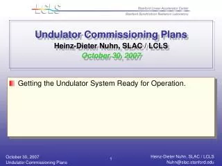
Undulator Commissioning, Alignment and Performance. Heinz-Dieter Nuhn – LCLS Undulator Group Leader August 27, 2009. All 33 Undulator Segments Operational. Girder Components. BFW. Undulator Segment. Part of WPM Support. RF Cavity BPM. Quadrupole and horz/vert Correctors. Segment Slider.

E N D
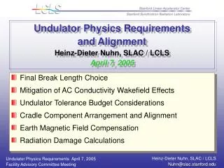
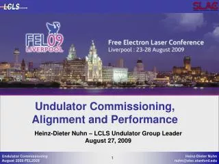
Undulator Commissioning, Alignment and Performance Heinz-Dieter Nuhn – LCLS Undulator Group Leader August 27, 2009
Girder Components BFW Undulator Segment Part of WPM Support RF Cavity BPM Quadrupole and horz/vert Correctors Segment Slider Girder Girder Mover (cam) HLS Sensor
Undulator Beam Operation Highlights • December 13, 2008 • First electron beam through undulator vacuum chamber without undulator segments. • No extra steering corrections necessary to get 100% transmission to main dump. • Pre-beam girder alignment was sufficient. • April 10, 2009 • First electron beam through undulator segments. • Detected FEL beam after 105 minutes, CCD saturation 20 minutes later.
Preparation for First Electron Beam • Extensive pre-beam checkout procedure • Precise girder alignment mapping (error ellipse about 50 µm) • Quadrupole position adjustment • to remove residual deviations from straight line as reported by last alignment mapping data. • to add offsets to compensate for the environmental fields (earth magnetic field etc.) as measured with field probe (five points per girder).
Undulator Line Alignment Overview Mount and precision-align Undulator, Quad, BPM and BFW on girder Align girders using conventional alignment to bring quadrupole centers onto straight line to 50 μm rms. Beam straightness requirement through undulator: 2 μm rms per field gain length (about 7 m) => Use Beam Based Alignment (BBA) with set of different energies for final quadrupole alignment Use BFW scans for upstream alignment. Quad/Corr BFW Undulator Segment RFBPM Res < 1 μm Beam Conventional Girder Alignment Grossly out of scale for clarity Wire inserted (One at a time) Wires extracted Ready for FEL After BBA: all Quads aligned After BFW scan/align
Beam Finder Wire Xray Scattering Electron Scattering
Beam Based Alignment Principle • BPM offsets unknown • Magnetic fields (earth, quad kicks, etc.) unknown • Task: Correct field integrals using quad offsets or correctors for dispersion free trajectory at BPM positions • Trajectory between BPMs remains unknown • Measure trajectory at different energies to extrapolate to straight line at infinite energy • Keep undulator quadrupole fields fixed • BPM position is BPM offset at infinite energy The following pages Illustrate the BBA Concept as implementedby Henrik Loos for the LCLS
BBA Measurement Schematic Measure (y) Dyj @ 4 Energies BPM Readings (each for h, v, and E) Solve Equations y = M x Obtain Results (x) Launch Parameters LE1, … , LE4 (Position & Angle; Energy dependent) BPM Offsets Δbi (each for h and v) Quad Offsets Δqj (each for h and v) Δb0 Δb1 Δb2 Δb3 Δb4 Δq1 Δq2 Δq3 E2 E1<E2 Positionsnot observable LE2 LE1 BPM Reading E1 Δy0 Δy1 Δy2 Δy3 Δy4
BBA M Matrix M = X Y × XH 0 MH YH = × XV MV YV 0
BBA Horizontal M Matrix = XH YH MH × XLHE1 XLHE2 MLHE1 YHE1 XLHE3 MQHE1 XLHE4 MB XDQ,H MLHE2 YHE2 = × MQHE2 MB MLHE3 XDB,H YHE3 MQHE3 MB Dimensions MLHE4 YHE4 MQHE4 MB C2 C1
BBA Horizontal M Sub-Matrices and Vectors Quad Mover Matrix Launch Trajectory Matrix 37 × 33 37 × 2 BPM Offset Matrix 37 × 37 if 0therwise Constraint Vector <y>=0 1 × 2 1 × 33 Launch Position Vector Constraint Vector 1 × 33
BBA Implementation • Setup accelerator for one energy • Calculate response matrix for this energy • Measure N trajectories at this energy and average • Repeat for all energies • Generate M-matrix with energy dependent elements and selected constraints • Add constraint equations for quad or BPM offsets • 0 = ΣiΔqi and 0=ΣiziΔqi for linear quad offset constraint • 0 = Δqi for minimum quad offset constraint • Fit quad and BPM offsets and implement • Repeat BBA procedure Fit solution for Δy arbitrary to adding linear function to quad and BPM offsets
BBA Result Measured Trajectories 4th Iteration Position rms 2 – 6 μm
BBA Results Fit with Linear Quad Constraint Offset Error Bar 10 μm
Quad Position/Kick Comparison Measured Quad Center Displacement to BBA Beam Undulator 1st Field Integral Tolerance: ±40 µTm Fitted 1st Field Integrals Quadrupole positions relative to the electron beam measured by changing the quadrupole gradient and fitting the kick angle. Kick angles are converted to field integrals between quads.As reference undulator segment first field integral tolerance is ±40 µTm .
Estimated Result of “Quad BBA” Estimate of the trajectory if instead of energy-dependent BBA the quadrupoles would have been moved to center them on the beam.The resulting trajectory is not dissimilar to the one we use to suppress FEL lasing. This illustrates the need for energy-dependent BBA!
Girder Stability : Position / Temperature • Girder component motion and undulator temperature variation change • the electron beam trajectory (phase errors) • due to changing quadrupole offsets • the undulator strength, which depends on • temperature • beam trajectory • Good News: Observed stability of quad positions and undulator temperatures is better than expected.
QU05 Stability Over 68-Hour Period The ADS is based on (1) two 140-m-long stretched wires carrying a 140MHz RF signal observed by four wire position monitors (WPMs) per girder and (2) a global water level system (HLS), also with four monitors per girder. The system has a 100nm resolution. The combined information from both subsystems is processed and continuously recorded. The graph shows, as an example, the recording of a 68-hour period during which no girder or segment was moved. 1 µm Horizontal Quad Position 24 hours Alignment Diagnostics System (ADS) 1 µm Alignment Diagnostics System (ADS) Vertical Quad Position 24 hours Quad Position Stability Tolerance 1 µm rms
U16 Temperature Stability over 15 day Period Tunnel Lights On 50 mK Temperatures are monitoredwith 12 sensors per girder 24 hours J. Welch presented poster about temperature control on Tuesday: TUPC53
Undulator Roll-Away and K Adjustment Pole Center Line Vacuum Chamber First; K=3.5000; Dx=-4.0 mm Neutral; K=3.4881; Dx= 0.0 mm Neutral; K=3.4881; Dx= 0.0 mm Neutral; K=3.4881; Dx= 0.0 mm Roll-Away; K=0.0000; Dx=+80.0 mm Horizontal Slide
Segmented Undulator K Control K ADJUSTMENT RANGE (MEASURED) TEMPERATURE CORRECTED KACT TAPER REQUEST K ADJUSTMENT RANGE (MEASURED)
Checking Undulator K Using YAG Luminescence* Yttrium K Edge at 17.038 keVequals 3rd harmonic of undulatorradiation at 11.286 GeV Expected Kund = 3.4926±0.0005 3rd harmonic ofSpontaneous Undulator Radiation on YAG Crystal Ee = 11.1 GeV Kmin =3.3532 Kavg =3.4616 Ee = 11.3 GeV Kmax =3.4256 Spontaneous Radiation fromDump Bend Ee = 11.5 GeV Ee = 11.7 GeV Ee = 11.9 GeV More precise bracketing gives Kavg =3.4932±0.0045 (1.7 ×10⁻⁴ from expected value) For detailed K measurements see talk by J. Welch in this session: THOA05 *by J. Welch and J. Frisch
Undulator Characterization: 1st Field Integral U09 Horizontal (I1X) and vertical (I1Y) first field integrals measured by fitting a kick to the difference trajectory as function of undulator displacement Reference Point Beam Based Measurements Requires 20 nm BPM resolution MMF Measurement
Radiation Control and Monitoring • Undulator radiation damage is greatly reduced through Machine Protection System (MPS) interlocks that inhibit beam to the undulator hall when • BLM (38 monitors) signals are above threshold • Beam loss fiber signals are above threshold • Horizontal and/or vertical trajectory is outside ±1mm • Comparator toroids indicate beam loss. • Any of the upstream profile monitors is inserted • More than 1 BFW is inserted or a BFW is moving • A regular TLD monitoring program is in place
TLD Readings at First Undulator Recorder Photon Doses about 0.1 rad per week
Dose During Initial FEL Operation [rad] e-folding length 8.7 m Increased TLD Readings are expected to be predominantly low energy synchrotron radiation, not to cause significant magnet damage
SN20 Radiation Damage Test HAS BEEN INSTALLED ON GIRDER 33 DURING FEL OPERATION Tol ±40 µTm ±50 µTm2 ±40 µTm ±50 µTm2 ±10° ±10° ±10° ±10° ±15×10-5 NO NOTICABLE CHANGE IN FIELD PROPERTIES DURING 2 MONTH OF FEL OPERATON
Alignment Tolerance Verification Beam Based Measurements Random misalignment with flat distribution of widh ±a => rms distribution a/sqrt(3)
Beam Based K Tolerance Verification Beam Based Measurements
LCLS Undulator Tolerance Budget BB Verification Tolerance Budget Components 0.06 1200 8.8 770 MEASUREMENTS
Summary • LCLS undulator system is successfully commissioned. • Initial beam operation went extremely smoothly: no tweaking required • BBA procedure is successfully implemented • Converges to ~1 μm trajectory rms • Important to have full energy range (4.30 GeV – 13.64 GeV) • BBA complemented by measurement of quad offsets by varying quad strength • Temperature and girder stability are well within tolerance • Beam loss control and radiation monitoring is in place • High radiation levels observed during FEL operation are predominantly low energy photons that are not expected generate demagnetization • Very low dose levels measured at electronics components • Several undulator tolerances could be verified with beam based measurements
Thanks to… The dedicated operations, metrology, engineering, controls, installation, and RF groups at SLAC The tremendous ANL undulator and BPM team The extraordinary commissioning team John Galayda (project director) for his leadership And many of you, who have contributed your ideas