The Delta Undulator
The Delta Undulator. A. Temnykh , CLASSE, Cornell University, Ithaca, New York, USA . *Work has been supported by NSF grant DMR 0225180 and PHY-013150. Concept . Two adjustable phase undulators * assembled in one device**. 30 cm long model built in Cornell.

The Delta Undulator
E N D
Presentation Transcript
The Delta Undulator A. Temnykh, CLASSE, Cornell University, Ithaca, New York, USA *Work has been supported by NSF grant DMR 0225180 and PHY-013150
Concept Two adjustable phase undulators* assembled in one device** 30 cm long model built in Cornell • Compact box-like frame (prototype has dimensions ~150mmx150mm) • Full polarization control • Sqrt(2) stronger field in planar mode and ~2X stronger in helical mode in compare with conventional Apple II type undulators. Project was motivated by the Cornell ERL needs. *R. Carr, Adjustable phase insertion devices as X-ray sources, Nucl. Instr. And Meth. A 306(1991) 391-396 **A. Temnykh, Delta undulator for Cornell energy recovery linac , Phys. Rev. ST Accel. Beams 11, 120702 (2008)
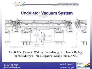
Beam test in BNL (ATF) Model in vacuum vessel Transport from Cornell to BNL Delta undulator installed in BL2 ATF. First harmonics in planar and helical mode 5300nm wavelength radiation as function of the electron beam energy. Signal confirmed 1.28T peak field in undulator 4520nm (bottom) and 3600nm (right) wavelength radiations versus beam energy. Both data confirmed 0.93T field amplitude. A. Temnykh, et al., Delta undulator model: Magnetic field and beam test results. Volume 649, Issue 1, 1 September 2011, Pages 42-45
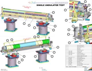
Delta Undulator for SLAC (development underway) Four movable magnet arrays mounted inside box like frame. Two 1.65m long sections connected together Magnet array mover (electrical cylinder) 4 5 3 1 2 1 – Rectangular frame 2 - Linear bearings 3 – Movable plates 4 – copper holders 5 – PM (NdFeB) blocks
Basic Parameters • Bore diameter - 6.4mm* • PM material - NdFeB 40SH (or 40UH) • Period - 32mm* • Two sections 1.65m each (3.3m total)* • Full polarization control • Peak field in helical mode 0.898 T, peak field in planar mode 1.270 T * Under discussion
PM material chose Br as function of coercivity Source http://www.cy-magnetics.com NdFeB – is the best chose Progress in PM material development
NdFeB grade Source http://www.kjmagnetics.com/specs.asp PM materials NdFeB 40SH or N40UH seem a reasonable compromise between magnetization strength and stability. UH – is more stable, but ~3X more expensive N40SH N40UH Source http://www.electronenergy.com/media/N40SH.pdf Source http://www.cy-magnetics.com
Undulator Period definition(result of 3D magnetic field modeling) Model parameters: Br = 12.6kG (low limit), bore diameter = 6.4mm For wavelength calculation in helical mode used: We need 1.5nm wavelength in helical mode (K=2.466) and K=3.5 in planar. For 32mm period there will be ~10% margin for the field strength
Magnetic field properties (field on beam axis) Bx,y,z in helical mode Bx,y,z in planar mode
Magnetic field properties (field roll-off) For 100mm trajectory offset in helical mode dB/B ~1.7e-4 and in planar mode ~1.0e-4
Reverse field effect analysis Single H-block Single V-block Bx_min = 5.3kGs => reverse field -7.3kOe, T_demag ~150degC for 40SH T demag ~ 180degC for 40UH By_min=5.1kGs => reverse field -7.5kOe T_demag ~145degC for 40SH T demag ~ 175degC for 40UH Undulator demagnetization temperature (reverse field effect) for various modes
Radiation damage consideration • The measured correlation between radiation dose (high energy electrons) and demagnetization temperature Copy from paper * For 100degC demagnetization temperature the critical dose (1% demagnetization) ~ 1Mrad *A. Temnykh, Measurement of NdFeB permanent magnets demagnetization induced by high energy electron radiation, NIMA Volume 587, Issue 1, 11 March 2008, Pages 13-19
Peak field on beam axis Magnetic Forcesfor 1 period / for 51 periods
Mechanical structure deformation under magnetic force load (stress analysis) Base plate deformation Frame deformation Helical mode Helical mode Maximum deformation ~0.6mm Maximum deformation ~0.7mm Planar mode Maximum deformation ~6mm Maximum deformation ~4.8mm
Conclusion Project is feasible Acknowledge Many thanks to Jim Welch, Heinz-Dieter Nuhn, Zack Wolf, YuriiLevashov and other people for interest in this project, invitation to work in SLAC and help.
PM block soldering technique 1 2 Single NdFeB (40SH) PM block, T_demag ~ 1320C PM block in steel jacked, T_demag ~ 2280C ! 63Sn/37Pb alloy melting point 182degC (US Patent 7,896,224)
Hall probe measurement setup for Delta http://www.lakeshore.com/mag/hs/hsts.html Hall probe sensor Ceramic tubing
CHESS Compact Undulator PPM structure, 24.4mm period, 1.1T peak field, 5mm constant gap . Dimensions: 1m x 152mm x 146mm, Weight - 83kg (with driver attached)