Download
1 / 30
370 likes | 836 Views
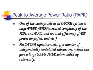
Peak-to-Average Power Ratio ( PAPR). 2012/07/30 邱營棋. Multi-carrier systems. The complex baseband representation of a multicarrier signal consisting of N subcarriers is given by where is the subcarrier spacing.

E N D
Peak-to-Average Power Ratio(PAPR) 2012/07/30 邱營棋
Multi-carrier systems • The complex baseband representation of a multicarrier signal consisting of N subcarriers is given by where is the subcarrier spacing. • In OFDM systems, the subcarriers are chosen to be orthogonal. (i.e., )
The effect of high PAPR • Due to the large number of sub-carriers in typical OFDM systems, the amplitude of the transmitted signal has a large dynamic range, leading toin-band distortion andout-of-band radiation when the signal is passed through the nonlinear regionof power amplifier. • Although the above-mentioned problem can be avoided by operating the amplifier in itslinear region, this inevitably results in a reduced power efficiency. • The PAPR of the transmit signal is defined as
AM/AM distortion Soft limiter
PAPR in discrete-time case • If we sample x(t) by a sampling rate of 1/Ts (the sampling period Ts= T/N ), we may miss some signal peaks and get optimistic resultsfor the PAPR. • For better approximating the true PAPR in the discrete-time case,we usually oversample x(t)by a factor of L , i.e., the sampling rate isL/Ts . • It was shown in [15] that an oversampling factor L=4is sufficient toapproximate the true PAPR.
PAPR in discrete-time case • For an OFDM system with N sub-carriers, an oversampling rate of L can be achieved by inserting (L-1)·N zeros in the middle of the modulated symbol vector to form a 1×LN data vector X, i.e. • The PAPR computed from the L-times oversampled time-domain signal samples is given by
The CCDF of the PAPR • The cumulative distribution function (CDF) of the PAPR is one of the most frequently used performance measures for PAPR reduction techniques. In the literature, the complementary CDF (CCDF) is commonly used instead of the CDF itself. • The CCDF of the PAPR denotes the probability that the PAPR of a data block exceeds a given threshold. • From the central limit theorem, the real and imaginary parts of the time domain signal samples follow Gaussian distributions, assuming each distribution with a mean of zero and a variance of 0.5 for a multicarrier signal with a large number of subcarriers.
The CCDF of the PAPR • Hence, the amplitude of a multicarrier signal has a Rayleigh distribution, while the power distribution becomes a central chi-square distribution with two degrees of freedom. • The CDF of the instantaneous power of a signal sample is given by • The CCDF of the PAPR of a data block with Nyquist rate sampling is derived as This expression assumes that the N time domain signal samples are mutually independent and uncorrelated.
PAPR Reduction Methods • Distortion • Clipping • Companding • Distortionless • Selected Mapping (SLM) • Partial Transmit Sequence (PTS) • Others • Active Constellation Extension (ACE) • Tone Reservation (TR)
Clipping • The simplest way to reduce the PAPR. • The peak amplitude becomes limited to a desired level. • Clipping • Clipping Ratio
Clipping • By distorting the OFDM signal amplitude, a kind of self-interference introduced that degrades the BER. • Nonlinear distortion increases out-of-band radiation.
Selected mapping (SLM) 1. A set of U markedly different, distinct, pseudo-random but fixed vectors P(u) = [P0(u) ,…, PN-1(u)], with must be defined. 2. The subcarrier vector Ais multiplied subcarrier-wise with each one of the U vectors P(u), then resulting to component 3. Then all U alternative subcarrier vectors are transformed into time domain to get and finally that transmit sequence with the lowest PAPR is chosen. • For implementation, the SLM technique needs U IDFT operations,and the number of required side information bits is , denotes the smallest integer that exceed y.
PAPR reduction performance of SLM • N = 256, L = 4, 16-QAM,
Partial transmit sequence (PTS) 1. In this scheme, the subcarrier vector A is partitioned into M pairwise disjoint subblocks All subcarrier positions in which are already represented in another subblock are set to zero, so that 2. We introduce complex-valued rotation factors , and μis index of all phase rotation of “Peak value optimization”. Enabling a modified subcarrier vector which represents the same information as A, if the set (as side information) is known for each μ.
Partial transmit sequence (PTS) 3. To calculate , the linearity of the IDFT is exploited. Accordingly, the subblocks are transformed by M separate and parallel N-point IDFTs, yielding 4. Based on them a peak value optimization is performed by suitablychoosing the free parameters such that the PAPR is minimizedfor . • It should be noted, that PTS can be interpreted as a structurally modified special case of SLM.
Partial transmit sequence (PTS) • In general, the selection of the phase factors is limited to a set with afinite number of elements to reduce the search complexity. • The set of allowed phase factors is written as , where W is the number of allowed phase factors. • In addition, we can set without any loss of performance. • Hence, sets of phase factors are searched to find the optimumset of phase factors. • PTS needs M IDFT operations for each data block, and the numberof required side information bits is .
PAPR reduction performance of PTS • N = 256, L = 4, 16-QAM, exhausted research for . W=2 means [+1,-1], W=4 means [+1, -1, +1j, -1j].
Active Constellation Extension (ACE) • In this technique, some of the outer signal constellation points in the data block are dynamically extended toward the outside of the original constellation such that the PAPR of the data block is reduced. QPSK 16-QAM
Active Constellation Extension (ACE) clipping PAPR
PAPR reduction performance of ACE • N = 256, L = 4, QPSK, A = 4.86 dB. PAPR
Tone Reservation (TR) • The transmitter reserves a small number of unused subcarriers. These subcarriers are referred to as peak reduction carriers (PRCs). • Since PRCs do not carry data, this increment induces a severe degradation of system’s power efficiency. • In general, there are two approaches to reduce the PAPR in the TR technique. • The first is to select the PRC indices for the TR technique to be used in reducing the PAPR. • The second is to design the proper values on these PRCs to generate an optimalpeak-canceling signalthat minimizes the PAPR of a transmitted OFDM signal.
Reference • [1] S. H. Han and J. H. Lee, “An overview of peak-to-average power ratio reduction techniques for multicarrier transmission,” IEEE Wireless Commun., vol. 12, pp. 56-65, Apr. 2005. • [2] T. Jiang and Y. Wu, “An overview: peak-to-average power ratio reduction techniques for OFDM signals,” IEEE Trans. Broadcast., vol. 54, no. 2, pp. 257-268, Jun. 2008. • [3] J. Armstrong, “Peak-to-average reduction for OFDM by repeated clipping and frequency domain filtering,” IETElectron. Lett., vol. 38, no. 5, pp. 246–247, Feb 2002. • [4] X. Li and L. J. Cimini, “Effects of clipping and filtering on the performance of OFDM,” IEEECommun. Lett., vol. 2, no. 5, pp. 131–133, May 1998. • [5] X. Huang, J. H. Lu, J. L. Zheng, K. B. Letaief, and J. Gu, “Companding transform for reduction in Peak-to-Average power ratio of OFDM signals,” IEEETrans. WirelessCommun., vol. 3, no. 6, pp. 2030–2039, Nov. 2004. • [6] T. Jiang and G. Zhu, “Nonlinear companding transform for reducing peak-to-average power ratio of OFDM signals,” IEEETrans. Broadcast., vol. 50, no. 3, pp. 342–346, Sep. 2004. • [7] S. S. Yoo, S. Yoon, S. Y. Kim, and I. Song, “A novel PAPR reduction scheme for OFDM systems: selective mapping of partial tones (SMOPT),” IEEE Trans. Consum. Electron., vol. 52, no. 1, pp. 40–43, Feb. 2006. • [8] M. Breiling, S. H. Muller, and J. B. Huber, “SLM peak-power reduction with explicit side information,” IEEE Commun. Lett., vol. 5, no. 6, pp. 239–241, June 2001.
Reference • [9] S. G. Kang, J. G. Kim, and E. K. Joo, “A novel subblock partition scheme for partial transmit sequence OFDM,” IEEE Trans. Commun., vol. 45, no. 9, pp. 333–338, Sep. 1999. • [10] A. Ghassemi and T. A. Gulliver, “A low-complexity PTS-based radix FFT method for PAPR reduction in OFDM system,” IEEE Trans. Signal Process., vol. 56, no. 3, pp. 1161–1166, Mar. 2008. • [11] B. S. Krongold and D. L. Jones, “PAR reduction in OFDM via active constellation extension,” IEEE Trans. Broadcast., vol. 49, no. 3, pp. 258–268, Sep. 2003. • [12] A. Saul, “Generalized active constellation extension for peak reduction in OFDM systems,” in Proc. 2005 IEEE International Conferenceon. Communications (IEEE ICC 2005), Seoul, Korea, Sep. 2005, vol. 3, pp. 1974–1979. • [13] J. Tellado, “Peak to average power reduction for multicarrier modulation,” Ph.D. dissertation, Stanford University, 2000. • [14] L. Wang and C. Tellambura, “Analysis of clipping noise and tone-reservation algorithms for peak reduction in OFDM systems,” IEEETrans. Veh. Technol., vol. 57, no. 3, pp. 1675–1694, May 2008. • [15] C. Tellambura, “Computation of the continue-time PAR of an OFDM signal with BPSK subcarriers,” IEEE Commun. Lett., vol. 5, no. 5, pp. 185–187, May 2001.