Download
1 / 29
290 likes | 390 Views

E N D
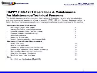
HAPPY HCS-1201 Operations & MaintenanceFor Maintenance/Technical PersonnelThis guide is intended to provide convenient, clearly-written and illustrated instructions for procedures that maintenance personnel are required to know for servicing HAPPY HCS-1201 Voyager. It does not replace the factory-developed maintenance manual, which remains as the principal technical reference for this machine. Electronic Updates / Procedures • Removing Voyager’s outer covers 2 • Starting the machine in Maintenance Mode 4 • Firmware Update – (by CF Card/Jump Drive) 5 • Firmware Update – (by CN-ROM chip) 7 • Needle Memory reset 9 • Speed and System reset 9 • Memory Re-initialization from Maintenance Mode Mechanical Procedures / Replacements • Rotary hook timing 10 • Hook retainer adjustment 13 • Presser foot height inspection and adjustment 14 • Needle Depth inspection/ Depth Gauge / Knowledge 16 • Moving Knife – about, timing and adjustment 20 • Knife Base: Exchange / Knowledge 24 • Needle bar boss / fixing boss jams 25 Other • Error Code List (Updated as of Feb 2010) 26 Chapter 4: Troubleshooting & Maintenance
3. Separate the locking tabs joining the left and right side covers at these locations. Removing Voyager’s Outer Covers • Remove the left-side cover first. (side without control panel). This can be done without removing the other side. • Some repairs including moving knife timing can be made by removing only this side cover. For some of the procedures in this guide, it may be necessary to remove Voyager’s outer covers. 1. Remove the thread stand and base. Then the bobbin winder. First, remove the bobbin winder tension knob. Then, insert a flat-tipscrewdriver into the slot on the tension knob shaft to and loosen before removing. 2. Next, remove these 2 screws (indicated by the red arrows) Chapter 4: Troubleshooting & Maintenance
Removing Voyager’s Outer Covers • Remove the right-side cover. (side with control panel). Note: This cover can be freed enough without removing the control panel to allow some common repairs: CPU board re-set/replace; serial/usb circuit board. Needle change cam repairs, presser foot motor. 1. Disconnect data cable shown. 3. Remove manual color change knob with 1.5mm hex wrench. 2. Disassemble and remove LCD panel from arm. (Detailed procedure not shown in this guide. (Continued) 6. Disconnect cable at rear for USB/serial LAN ports. 5. Remove 3 internal screws shown here. 4. Remove screw shown. Chapter 4: Troubleshooting & Maintenance
Calendar Network System Speed Version Maintenance Maintenance Electronic Updates through Maintenance Mode • Entering Maintenance Mode • Follow these steps: • Power off the machine. • Press and hold the MENU key while powering the machine back on. • The normal startup screen appears. Press the SET key to continue as normal. • Navigate to the OTHER sub-menu. A new option will appear as shown on the right: • Choose Maintenance and pressSET. • Enter code 2251 using the 4 arrow keysand press SET. • The Maintenance Screen appears, from which you can perform different electronic adjustments. Key electronic adjustments can be made on Voyager through Maintenance Mode. Refer back to the procedure on this page for other key procedures later on in this guide. [Maintenance] Input Code2251 [Maintenance] Machine: A Angle: 0 Memory: Display: > Install: Record: Chapter 4: Troubleshooting & Maintenance
Electronic Updates: Firmware Updates • Firmware Update via CF Card or Jump Drive • This method is the most convenient, requiring no machine disassembly. For the update, the correct update files for the above 4 must be saved onto the ROOT DIRECTORY of a compatible CF card or USB jump drive (if the machine has a USB jump drive port). There are 2 files for each section – a .bin file (the actual data) and a .upi file (updater file). A complete set of update files might look like this below: • LCD Controller update files: LCDHA103.bin LCDHA103.upi • Language update files: H_eng160.binH_eng160.upi • CPU board control updates: Chcsa114.binChcsa114.upiOn-board lettering updates: Ltr101.bin Ltr101.upiVersion numbers may vary for different updates. The file versions listed above are correct for firmware version 1.14, which is current as of January 2010 for color monitor versions of Voyager. • Procedure • Save the above files onto a CF card or USB Jump Drive (on the drive’s root directory) and insert the card or drive into the machine. • Start the machine in maintenance mode (as described on the previous page) HAPPY provides updates to Voyager’s on-board firmware for functional improvements and occasional bug fixes. The firmware can be updated either through a CompactFlash card, Jump Drive, or in cases when the machine cannot be re-started, by flashing from a CNROM chip on the internal CPU board. The firmware updates are divided into the following sections: (1) LCD Control program; (2) Language; (3) CPU board control program and (4) on-board lettering Chapter 4: Troubleshooting & Maintenance
Electronic Updates: Firmware Updates • Firmware Update via CF Card or Jump Drive (continued) • 3. Update the Language File first. From the Maintenance screen, choose Install, then Install from the sub-menu. Then, choose the update file for language. The language file name will start with the letters “Eng” for English, “Spa” for Spanish, etc. • Note that only 1 file shows (the bin file) for each stage. After pressing , the message “installing data” appears. Wait until the update is complete and let machine re-boot automatically, prompting you to press SET to return to the main Drive screen. Before continuing to the next stage, be sure to shut down again and re-boot into Maintenance mode. • 4. Update the ATA Board Controller Program. This step is similar to the language program update – from the Maintenance screen, choose Install, then Install again. Choose the file with the name starting with “LCDHA”, as shown here. Again, wait until the process completes – the machine will re-boot again, and you’ll have to shut down again and re-start in Maintenance mode to continue to the next stage. [Maintenance] [Maintenance] [ Install Mode ] Machine: A Angle: 0 Memory: Display: > Install: Record: - - Installing Data - - > 1: eng160 Install: prog: letter font: SET Auto re-boot [Maintenance] LCD Control Panel Installing [ Install Mode ] > 1: LCDHA103 Auto re-boot Chapter 4: Troubleshooting & Maintenance
Electronic Updates: Firmware Updates • Firmware Update via CF Card or Jump Drive (continued) • 5. Update the CPU control program. From the Maintenance screen, choose Install, then Prog from the sub-menu. Then, choose the update file for the CPU, with the name starting with “CHCS”. • Once again, wait until the update process completes before continuing. Note: At this stage the process is complete. The on-board lettering program may be updated here, but as of this writing, updates to this program have been frozen by HAPPY. • 6. Verify updates. After re-booting, you can check firmware version: from the main screen, press MENU, navigate to Other, then select Version to confirm the new firmware version#. • 7. Re-Set the machine. Perform a standard re-set of the machine from the main menu – press MENU, then choose OTHER and do the following: • - Select SYSTEM and press SET. This re-sets the on-board program instantaneously.- Select SPEED and press SET. This will re-set the firmware-to-inverter programming, running the machine gradually through its full speed range, then stop. Select OK at the warning “Caution: Main Shaft Turns”, to allow this to continue. The needle will not engage during this procedure, but the take-up lever will engage. [Maintenance] [Maintenance] Load 1.14 - - - - - - - - > Complete Choose “PROG” this time! [ Install Mode ] Machine: A Angle: 0 Memory: Display: > Install: Record: > 1: CHCS114 Install: prog: letter font: Chapter 4: Troubleshooting & Maintenance
Electronic Updates: Firmware Updates • Firmware Update via CN-ROM”Follow the procedures on this page to update Voyager’s firmwarevia CN-ROM. [Maintenance] Machine: A Angle: 0 >Memory: Display: Install: Record: • 1. Re-initialize machine memory. This will erase all designs. To do this, boot into Maintenance mode, and choose Memory. Follow the prompts to clear the memory. • 2. Power off the machine and open the control panel-side cover to expose the CPU board. Find the ROM socket on the CPU.3.Insert the CNROM CHIP, oriented with the notch facing downwards.4.Set DIP switches, then power on. Find the DIP switch panel on the lower-right corner of the CPU board, and set DS4 to “ON” and DS2 to “OFF”. Then, power on the machine.5. Allow process to complete, then power down.6. Reset DIP switches back: DS4 should return to the “OFF” position and DS2 should be set to “ON”.7. Remove ROM chip8. Clear Memory as performed in step (1) above.9. Re-Set Needle Position (see next section). To clear memory DIP switch settings for firmware update ROM chip inserted with notch facing downwards! ROM socket on CPU board Chapter 4: Troubleshooting & Maintenance
[Maintenance] > Machine: A Angle: 0 Memory: Display: Install: Record: Electronic Adjustments: Needle Memory • In cases where the machine loses “track “ of the correct needle position number (for example, control panel will show needle 12 while the head is actually positioned over a different needle), follow this procedure to re-set the needle memory of the color change potentiometer and cam. • 1. Move machine manually to needle 1 with the manual knob. • 2. Boot into maintenance mode as described on page 2. 3.Choose “MACHINE” from the maintenance menu and press SET. 4.Select option “D” using the arrow keys, then press SET.5.Move machine manually to needle 12 with the knob.6. Select option “E” using the arrow keys, then press SET.7. Select option “F” using the arrow keys, then press SET. This is a test function. Move the manual needle change knob to each needles. The screen should now display the proper needle number as it comes to rest over the needle plate. If it doesn’t, repeat the procedure. • 8. Press SET after checking, then choose “END” to exit the test mode.9. Restart the machine normally. Change to D, E, or F for steps 4-7 Electronic Adjustments: Speed Reset • In some cases, the inverter may revert to a mode that does not allow full sewing speed, often limiting speed to 500 stitchesper minute. This can result from either a fault or during certain normal maintenance procedures such as firmware updates. In such cases, the control panel provides an on-board re-set in normal operation mode. • 1. Go to the main menu by pressing MENU from the main Drive screen. Go to the 2nd screen of options.2. Select OTHER and press SET.3. Choose SYSTEM and press SET. Continue on to re-set the on-board program. This happens instantaneously and returns you to the boot screen. • 4. Return to the OTHER sub-menu as in steps 1 and 2 above. 5.Choose SPEED from the menu and press SET A warning will appear “Caution: Main Shaft Turns!”. Press SET to continue. The main shaft will start to turn and accelerate slowly to full speed (needle will not engage – only the take-up lever), then stop. Chapter 4: Troubleshooting & Maintenance
Electronic Adjustments: Memory Re-Initialization • MEMORY • The nature of storing electronic data sometimes creates opportunities for the machine to misinterpret the information it needs to process. Stored designs can develop “glitches” that will affect the performance of the machine or cause it to malfunction entirely. Re-initializing the memory can be a good resource for solving general machine malfunctions. Note: CPU Firmware Version 1.11 and later introduced improvements to make it easier to clear this memory. RE-INITIALIZING MACHINE MEMORYThere are 2 ways to do this, the simpler, more convenient way by booting the machine into a special maintenance mode and choosing the appropriate option to re-set memory. If, however, the control panel is completely inoperable, there is a way to re-set the machine directly on the control panel circuit board, which is outlined on the next page.Re-Initializing from “Maintenance” Mode1. Boot the machine into Maintenance mode. Do this by powering on the machine while pressing the MENU key. The machine will appear to start normally. On power-on, press SET to boot to the main (drive screen). Then, press MENU to access the main menu, index to “OTHER” and press “SET”. Choose MAINTENANCE, then press SET. Enter access code 2251 and press SET. The machine is now in a diagnostic/maintenance mode. • 2. Re-set the machine memory. In the menu that appears, index to MEMORY and press SET. Follow the screen prompts afterwards to clear machine memory. • 2. Re-initialize machine settings according to the procedure on page 18. • 3. (Optional) Reset needle detection. This is sometimes necessary to after a memory re-initialization. Chapter 4: Troubleshooting & Maintenance
Electronic Updates: Memory Re-Initialization • RE-INITIALIZING MACHINE MEMORY (continued)Hardware-Re-Initialization of Machine Memory from the control panel circuit board 1. Turn the machine off.2. Remove the four screws on the control panel. Do this using a phillips screw driver. The screws are located near each corner at the rear of the control panel. • 3. Separate the monitor. Do this by gently leaning the monitor away from the LCD board and rear of the control panel. Be aware of the delicate wires that connect the two halves. • 4. Turn dip switch-1 down. • 5. Turn the machine on. Then press the Set button. The machine will display “Data Initialize”. • 6. Turn the machine off.7. Turn dip switch-1 up.8. Reassemble the monitor. Do this by reinstalling each of the four screws at the rear of the control panel.9.(Optional) Reset needle detection. It is sometimes necessary to reset the needle detection after a memory re- initialization (refer to page 16) Chapter 4: Troubleshooting & Maintenance
Mechanical Procedures: Rotary Hook Timing • The precise timing wheel on Voyager (and other HAPPY machines) makes it possible for your customers to check hook timing, allowing troubleshooting hook-related issues over the phone before visiting the customer site – the short procedure is outlined below. On the following page are the procedures for adjusting hook timing. • Checking Rotary Hook Timing and ClearanceIf you suspect that your rotary hook timing is off, you or your customer can check this easily yourself following these steps: • 1. Power the machine on and allow it to continue to the main drive screen. • 2. Select needle six (6). Do this using the keys on the control panel • 3. Remove the needle plate and bobbin case . Do this by loosening each of the two (2) flathead screws with an offset screwdriver (provided in the machine’s toolkit) • 3.Remove the bobbin case. • 4. Engage the needle. Do this by pressing the P.FOOT key, which lowers the presser foot. Then, grab the needle bar over the presser foot, and pull it down until it locks into place. • 5.Turn shaft to 25 degrees. Do this with a 3mm Allen wrench. Turn the main shaft from the rear of the machine clockwise to L+25 (25 degrees). The needle should be down and in the basket area of the rotary hook at this point. Timing for HCS-1201 is at 25 degrees. With the needle engaged, it should fall into this basket in front of the rotary hook and just behind the retaining finger. Chapter 4: Troubleshooting & Maintenance
Mechanical Procedures: Hook Timing • Checking Rotary Hook Timing (continued) • HOOK-NEEDLE CLEARANCE (front-back) at 25 degrees:From the side of the machine, the point of the rotary hook should be approximately 0.1-0.15mm from the back of the needle (about the thickness of a business card). If the point is either touching or too far from the needle, the machine is not set correctly and will require adjustment. • TIMING (left-right) at 25 degrees:Viewing the hook assembly from the front of the machine, the point of the rotary hook should be hidden behind the needle. Note that the hook point passes behind the needle across the lower portion of the scarf. This clearanceshould be about the width of a business card. Chapter 4: Troubleshooting & Maintenance
Mechanical Procedures: Hook Timing • Adjusting Rotary Hook Timing • 1. Loosen the Rotary Hook. Do this by loosening each of the three (3) set screws that attach the rotary hook to the rotary hook shaft. Start with the larger screw on the milled flat spot of the hook’s neck (lower right). Loosen screws just enough to break the hook loose on the shaft. Turn the wheel as necessary to access each screw from either side. 3. Reset the dial to 25 degrees. Check that the needle is lowered into the rotary hook basket once more and that the main shaft dial is set 25 degrees. Adjust the main shaft as necessary by hand at rear of the machine. • 4. Move hook and tighten screws. Adjust the timing and clearance simultaneously according to the diagrams on the previous page. Tighten screws carefully. If necessary, have an assistant hold the main shaft exactly at 25 degrees while positioning and tightening. • Helpful Hints - Have a helper hold the timing wheel at 25 degrees with the T-handle wrench as you make your adjustments and tighten the screws. - Tighten each screw just enough to snug the hook back on the shaft, then re-check the timing, then tighten each screw further. Tighten all screws as firmly as you can manage. When practicing, re-check constantly as each screw is tightened. - Use a quality flat-tip screwdriver with a wide grip to help you apply enough torque to secure the rotary hook tightly on the shaft. (3/4 view) 3 set screws are located along the rear “collar” of the rotary hook. (side view) Turn the hook as necessary for easy access with a screwadriver. Loosen this screw first before the other 2. Chapter 4: Troubleshooting & Maintenance
Mechanical Procedures: Hook Retainer Adjustment Stub of hook retainer About the Hook Retainer (also called retaining finger)The hook retainer is located at the front of the rotary hook, near thetop of the bobbin case. It is responsible for keeping the inner basket and bobbin case from spinning freely, while still allowing thread to pass across the front of the rotary hook. • Adjusting the Hook RetainerFollow this short procedure to adjust the hook retainer: • 1. Remove the needle plate. Do this by loosening each of the two (2) flathead screws with an offset screwdriver. • 2. Loosen the black screw. But do not remove. This will be the small button head hex screw toward the right corner, facing downward. • 3. Move the retainer. Looking downward, set the stub located at the center of the retainer to approximately 0.8mm from the back edge of the rotary hook basket; or about halfway into the basket. The photo on the lower right shows a retaining finger close-up with proper clearance. • 4. Tighten Screw. And check that the inner basket of the rotary hook does not rotate freely. Hook retainer or retaining finger Location of black set screw Photo of clearance of retaining finger stub from the notch in the hook. Location of black set screw Side view, retaining finger Chapter 4: Troubleshooting & Maintenance
Mechanical Procedures: Presser Foot Inspecting Presser Foot HeightFollow this procedure to check proper presser foot height: 1. Engage the needle. Do this by pressing the P.FOOT key, which lowers the presser foot. Then, grab the needle bar over the presser foot, and pull it down until it locks into place. 2. Turn the shaft to 0 degrees. Do this with using a 3mm hex wrench to turn the timing wheel at the rear of the machine. 3. Check the clearance. The distance between the plate and pressure foot should be approximately 1.2mm; or slightly less than the width of a dime. Chapter 4: Troubleshooting & Maintenance
Mechanical Procedures: Presser Foot Turn knob to index the head past needle , exposing the set screw for the presser foot shaft. • Adjusting Presser Foot Height1. Take note of the adjustment needed by completing| steps 1-3 on previous page. • 2. Return the needle to the home position by pressing the T.CUT button or manually turning the shaft to 270 deg. as indicated by the timing wheel at the back. This MUST be done before performing step 4 below. • 3. Remove retaining clip shown with a 1.5 mm hex wrench, from the end of the metal guide rail on the control panel side of the moving head. • 4. Index the head past the needle 1 position to needle“0”. Do this by turning the manual needle select knob clockwise. • 5. Loosen the set screw and adjust the presser foot height. This is a phillips-type screw that fastens the pressure foot to the needle bar. Do not remove the screw. Adjust until the clearance measures approx. 1.2 mm or slightly less than the width of a dime. • 6. Tighten the set screw. Remove this retaining clip with a 1.5 mm hex wrench. Exposed 2mm Hex set screw Chapter 4: Troubleshooting & Maintenance
Mechanical Procedures: Needle Depth Inspecting Needle DepthIt may be useful to obtain a needle depth gauge to check this more easily. 1. Engage the needle. Do this by pressing the P.FOOT key, which lowers the presser foot. Then, grab the needle bar over the presser foot, and pull it down until it locks into place. 2. Turn the shaft to 5 degrees. Use a 3mm hex wrench to turn the timing wheel at the rear of the machine. 3. Check needle depth. Inserting the plastic depth gauge into the rotary hook. The tip of the needle should lightly scratch the surface of the gauge. Needle depth gauge Chapter 4: Troubleshooting & Maintenance
Mechanical Procedures: Needle Depth • Adjusting Needle Depth1. Prepare the machine. Do this by completing steps 1-3 on the previous page. • 2. Remove the lower faceplate. Follow the procedure below to do this. Careful – the lower faceplate will fall. Be ready to either hold the lower plate aside or leave unthreaded. Remove the 2 screws along the bottom edge of the lower faceplate. Remove these 2 screws along the control-panel side of the lower faceplate. The correct upper boss screw is now exposed for adjustment. • 3. Loosen the upper needle bar boss, and adjust. Do NOTloosen the lower needle bar boss.Continue to adjust until the needle lightly scratches the gauge. • 4. Tighten the upper needle bar boss. Make certain to aim the needle forward to its original position before tightening. Chapter 4: Troubleshooting & Maintenance
Mechanical Procedures: Moving Knife Timing About the Moving KnifeThe moving-knife is located beneath the needle plate and is responsible for trimming both the upper and bobbin thread simultaneously. It works by catching these two threads and drawing them back toward the black fixed-knife (not shown). The moving-knife creates a scissoring action as it slides beneath the fixed-knife, returning to its closed position. The knife must open and close at a precise moment for a trim to occur. When the knife timing is not adjusted correctly, the machine will generally fail to cut, producing knife and catcher errors. The knife action is engaged by a long arm reaching towards the back of the machine – a solenoid turns and pushes a pin roller upwards, where it fits into a the groove of a cam mounted on the main shaft. As the main shaft turns with this locks together, the groove’s zig-zag shape pushes the knife arm forwards and backwards, creating the scissoring action. Trim Cam. Mounted on back of main shaft. Imparts back-and-forth motion on lever system with turning groove. Collar. Locks trim cam onto main shaft. Loosen from set screw. Roller pin in lowered, disengaged position. Manual engagement lever. (shown in green, but actually white) allows you to engage the trim cam manually to re-set the trim system. Set screw For trim cam collar. Trim cam Collar (holds trim cam in place on shaft) Trim Solenoid. Engages the roller into the cam. Roller pin in raised (engaged) position, now inside groove of trim cam. Engagement roller pin. Is raised manually or by solenoid into groove of trim cam Drive arm. Swivels in place during the trim cycle to move the drive link assembly CONTROL PANEL SIDE FRONT OF MACHINE Moving knife (shown in open position) Chapter 4: Troubleshooting & Maintenance
Mechanical Procedures: Moving Knife Timing INSPECTING KNIFE TIMINGFollow the procedure below to check moving knife timing. Refer to the diagram on the previous page. 1. Remove the needle plate. Do this by loosening each of the two (2) flathead screws with an offset screwdriver. This will allow you to observe the action/position of the moving and fixed knives.2. Assemble the manual engagement lever. Do this by attaching the white knob to the Lever (red arrow on right) This allows you to cycle the trimmer manually to re-set the trim system. The knob is white and plastic, and attaches to the lever that is exposed through the small access hole near the bottom edge of the left hand cover. 3. Turn main shaft to 90 degrees with a 3mm Allen wrench. Turn the shaft from the rear of the machine clockwise to L+90 (90 degrees). 4. Engage the lever. Do this by pressing the white knob down and maintaining pressure. 5. Turn main shaft to 116 degrees. Turn the main shaft from the rear of the machine clockwise to L+116 (116 degrees). The moving-knife should begin to open at this point and there should be some resistance on the main shaft. 6. Turn shaft to a few more degrees. From L+116, continue turning the main shaft clockwise. If the moving-knife is still not opening, the knife timing must be adjusted. Press and hold after turning shaft to 90 degrees, then continue turning main shaft. Knife should start swiveling out from under fixed knife around 116 degrees. Chapter 4: Troubleshooting & Maintenance
Mechanical Procedures: Moving Knife Timing ADJUSTING KNIFE TIMINGFollow the procedure below to adjust moving knife timing. 1.Remove the needle plate. Do this by loosening each of the two (2) flathead screws with an offset screwdriver. 2.Remove the control panel-side side cover (following procedure on page 3. You may also remove the power supply unit to provide more working space (optional, shown below). Next, remove the 2 mounting screws. There is 1 shown here, and and additional 1 where it joins the main motor Finally, remove this small cover – there are 2 phillips-type screws that hold it in place. First, unplug the power supply as shown. • 3.Depress the manual engagement lever. This can be performed with or without the white plastic knob. The lever may not depress completely. Maintain constant downward pressure while performing steps 4 through 8 below.4. Turn the main shaft with a 3mm Allen wrench, clockwise until the manual engagement lever is completely down and the roller engages into the trim cam. Stop when there is resistance at the main shaft. • 5.Loosen the trim cam collar. Do this by loosening the corresponding set screw. (Note: on later-model Voyagers, this is actually 2 semi-circular shaped pieces joined by set screws at opposite ends – in which case, you can try still just loosening one of the screws. • 6. Turn shaft to 115 degrees. Turn the main shaft from the rear of the machine to L+115 (115 degrees). • 7. Position the cam. Do this by rotating the top of the cam toward you, until it stops against the roller pin, then maintaining light pressure to the left. • 8. Tighten the trim cam collar. Do this by tightening the corresponding set screw. • 9. Release the manual engagement lever. Chapter 4: Troubleshooting & Maintenance
Mechanical Procedures: Moving Knife Timing • ADJUSTING KNIFE TIMING(continued) • Shown below are diagrams for the procedure on the previous page – adjusting moving knife timing. Turn shaft until this screw is visible and loosen with a 3mm hex wrench. Trim cam and collar (indicated by arrow) Illustration: Notch in trim cam Illustration: Trim cam and collar fit (single-piece collar version) Chapter 4: Troubleshooting & Maintenance
Other Mechanical: Knife Base The knife base is the rigid platform above the rotary hook, on which the moving and fixed knife is mounted. The moving knife swivels around this vertical pin that runs down through the knife base. The knife base is fixed firmly to the front of the sewing arm by the hex screws shown above, indicated by the red arrows. Binding of the moving knife from hoop strikesSometimes during a hard, high-speed hoop strike, the metal bed of the knife base can bend, binding the swiveling pin and preventing the knife from moving. The entire knife base may have to be replaced. In some cases, the knife base can be bent back into alignment with the proper tools. Chapter 4: Troubleshooting & Maintenance
Other Mechanical: Upper & Lower Needle Bar Boss Upper needle bar boss As shown in the diagram here, the upper and lower needle bar bosses engaged to the fixed head and reciprocator, which have (roughly) c-shaped receptacles, as shown in these diagrams. Boss B assembly Lower needle bar boss(now disengaged)_ Disengaged positionNote that while the lower boss is now free from the reciprocator, the upper boss for the active needle is still engaged, even if the drive system isn’t engaged. Engaged positionWhile the machine is sewing, the active needle bar is connected to the drive system at both the upper and lower boss. The lower boss is locked into the reciprocator. Both upper and lower needle bar bosses are engaged during sewing. Reciprocator The moving knife swivels around this vertical pin that runs down through the knife base. Problem area: Boss Jam Sometimes during a hard, high-speed hoop strike or other incident, the upper boss becomes disengaged from the upper c-shaped clip (right side diagram). If so, it is necessary to move the head to a position (such as needle 0) to free the boss peg so that it can be manually locked back onto position. Chapter 4: Troubleshooting & Maintenance
Error Code List and Measures page 1 Chapter 4: Troubleshooting & Maintenance
Error Code List and Measures page 2 Chapter 4: Troubleshooting & Maintenance
Error Code List and Measures page 3 Chapter 4: Troubleshooting & Maintenance
Error Code List and Measures page 4 Chapter 4: Troubleshooting & Maintenance