Digital Inputs Interfacing Keypad
140 likes | 383 Views
Digital Inputs Interfacing Keypad. Khaled A. Al- Utaibi alutaibi@uoh.edu.sa. Agenda. The Phone Keypad Scanning the Keypad Interfacing the Keypad Reading the Keypad Input. The Phone Keypad. The phone keypad is a 4x3 key matrix consisting of 4 rows by 3 columns as shown in in the figure.

Digital Inputs Interfacing Keypad
E N D
Presentation Transcript
Digital InputsInterfacing Keypad Khaled A. Al-Utaibi alutaibi@uoh.edu.sa
Agenda • The Phone Keypad • Scanning the Keypad • Interfacing the Keypad • Reading the Keypad Input
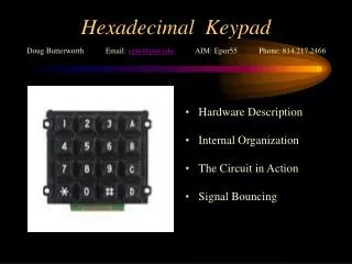
The Phone Keypad • The phone keypad is a 4x3 key matrix consisting of 4 rows by 3 columns as shown in in the figure. • When a key is pressed it connects its column pin to its row pin. • For example, when key 5 is pressed it connects column 2 pin to row B pin.
Scanning the Keypad • When interfacing the keypad to a microcontroller, we need to determine which key is pressed. • This can be done using a very simple procedure called "key scanning". • The procedure is performed as follows: • (1) Apply Logic 1 on column 1 and Logic 0 on remaining columns. • (2) Scan the logic signals on all rows A to D. • (3) If a Logic 1 is read on one row then this indicates that the corresponding key (i.e. 1, 4, 7 or *) is pressed. For example if Logic 1 is read on Row B then this indicates that key 4 is pressed. • (4) Repeat steps 1-3 for column 2 to determine if any of the keys (2, 5, 8 and 0) is pressed. • (5) Repeat steps 1-3 for column 3 to determine if any of the keys (3, 6, 9 and #) is pressed.
1 0 0 Z 1 Z Z
Interfacing the Keypad • The phone keypad can be interfaced to the Arduino Uno Board as shown in the next slide.
Interfacing the KeypadDesign Example • Interface a phone keypad to the Arduino Uno Board and write a simple program to display the value of pressed key on the Arduino environment’s built-in serial monitor
Interfacing the KeypadDesign Example • The code that will scan the keys and display the value of the pressed key on the Arduino environment’s built-in serial monitor consists of the following main pars: • (1) Global variables declarations. • (2) Input/output pins configurations. • (3)Key scan logic. • (4) Key value display logic.
Keypad Scan ExampleGlobal Variables Declarations • In this part, an array is declared to hold character values corresponding to the buttons of the keypad // character values corresponding to the keypad buttons char[][] keypad = { {'1', '2', '3'}, {'4', '5', '6'}, {'7', '8', '9'}, {'*', '0', '#'} };
Keypad Scan ExampleInput/Output Pins Configurations • In this part, we configure the digital pins of the Arduino board to scan the keypad as follows: • Configure pins 0-2 as output pins to control COL1-COL3 of the keypad. • Configure pins 3-6 as input pins to read ROW1-ROW4 of the keypad. // set pins 0-2 as outputs to control COL1-3 of the keypad for(intcol = 0; col < 3; col++) { pinMode(col, OUTPUT); } // set pins 3-6 as inputs to read ROW1-4 of the keypad for(int row = 3; row < 7; row++) { pinMode(row, INPUT); }
Keypad Scan ExampleKey Scan Logic • In this part, we scan the keypad and return the character value of the pressed key or NULL if no key is pressed. • (1) Set key value to null • (2) For each pin 0-2 connected to COL1-3 do the following • (a) Set the column HIGH • (b) For each pin 3-6 connected to ROW1-4 do the following • Read the state of the row • If the state of the row is HIGH the do then set key value to the character corresponding to the pressed button • (c) Set the column back to LOW • (3) Return the key value
chargetKey() { // set key value to null charkeyValue = '\0'; // a variable to read the row state introwState; // for each pin 0-2 connected to COL1-3 do the following for(intcol = 0; col < 3; col++) { // set the column HIGH digitalWrite(col, HIGH); // for each pin 3-6 connected to ROW1-4 do the following for(int row = 3; row < 7; row++) { // read the state of the row rowState= digitalRead(row); // if the state of the row is HIGH the do the following if(rowState == HIGH) { // set key value to the character // corresponding to the pressed button keyValue= (keypad[row - 3][col]); } } // set the column back to LOW digitalWrite(col, LOW); } // return the key value return(keyValue); }
Keypad Scan ExampleDisplay Key Value Logic • In this part, we use the getKey() function to get the value of the pressed key: • Get key value using the function getKey(). • If the returned key value is not NULL then display the value on the serial monitor // get key value charkey = getKey(); // if the key value is not NULL then if(key != '\0') { // display the key value on the serial monitor Serial.println(key); }