Download
1 / 25
250 likes | 377 Views
ECAL Monitoring System. Ivan Korolko (ITEP Moscow) PRR, September 2004. Outline. Finalized light splitter Fiber bundles configuration Light distribution boxes LED drivers and PIN diode boards Planning. Light splitters. Produced and tested this summer. 1) Very simple construction

E N D
ECAL Monitoring System Ivan Korolko (ITEP Moscow) PRR, September 2004
Outline Finalized light splitter Fiber bundles configuration Light distribution boxes LED drivers and PIN diode boards Planning
Light splitters Produced and tested this summer 1) Very simple construction 2) Good uniformity of light yield for all fibers 3) Good reproducibility 4) High light yield
Light splitters uniformity ● central fiber ● 1st circle ● 2nd circle ● 1.2 mm fibers
Fiber bundles Corresponding number of fibers is grouped in bundle and molded with epoxy resin. Fibers in bundle have different length to lighten the connection to optical contacts. (max ~50cm) High temperature bending of fibers – technology optimization • requires quite some man power (now) • dangerous to break a fiber • HERA-B experience (curved fibers forming bundle)
Fiber bundles configuration (1) Outer and Middle sections: Splitters 1 → 16+3 Inner section: Splitters 1 → 9+3
Fiber bundles configuration (2) Inner section: reduced number of LEDs (factor 1.5)
LEDs PiN diodes Trigger signals Outer 84 28 84 Middle 56 14 56 Inner 88 22 88 Components of monitoring system
Routing of bundles (1) 25 mm trays for inner ECAL section
Routing of bundles (2) 37 mm trays for middle ECAL section
Routing of bundles (3) 45 mm trays for outer ECAL section
PiN diode board PiN diode Splitter LED LED driver LED-PiN fiber Bundles Light distribution box (fragment)
1st lower box Box size 720x880x120 Led driver 15x100 mm2 PIN diode board 40x100 mm2 Power for LEDs +5V, +25V Power for PINs +/-6V, +25V Trigger signals LED amplitude control voltages
LED drivers (1) Dedicated ECAL version of LED driver (produced in IHEP) Several LED drivers produced and tested during this summer beam tests
LED drivers (2) DS0026 became obsolete (still available from distributors) PCB design and prototypes exist for: • pin-to-pin compatible EL7212, ICL7667 • EL7104 • SN75372 DC isolation of the triggering signals requires individual triggering for each LED driver.
PIN diode boards (1) Dedicated ECAL version of PIN diode board (produced in IHEP) PIN diode boards produced and tested during this summer beam tests
PIN diode boards (2) Charge gain ~300 ENC ~5000 electrons δ function response ~10 ns. Dynamic range 12 bits The same clipping line as for PMTs is used Amplifiers are based on LMH6624 or EL5133
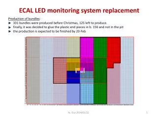
Planning (1) Many changes during last months ECAL installation should be finished on 31 of July The whole planning is quite tense
Planning (2) Production of bundles starting on 04/10/2004 special “long” room with shelves is ready Cutting of bundles starting on 25/10/2004 need to prepare cutting tools Should be finished in March Installation of bundles : 15/04/2005 – 15/05/2005
Planning (3) Detailed design of LDBs : 15/12/2004 meeting in Moscow or at CERN (Stas) Production of LDBs starting on 15/01/2005 Installation of LDBs starting on 15/05/2005 Final connection of all components 01/06/2005 – 01/07/2005
Planning (4) Production of LED housings 01/11/2004 – 1/03/2005 should be delivered to CERN in March LED drivers and PIN diode boards purchase of components – ASAP mass production 01/01/2005 – 01/03/2005 should be delivered to CERN in March temporary readout system to check the work of LEDs and PMTs ??? Seems to be useful ???