Download
1 / 20
230 likes | 293 Views
REGISTER TRANSFER AND MICROOPERATIONS. • Register Transfer Language • Register Transfer • Bus and Memory Transfers • Arithmetic Microoperations • Logic Microoperations • Shift Microoperations • Arithmetic Logic Shift Unit. Register Transfer Language. Registers (R). ALU (f).

E N D
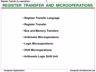
REGISTER TRANSFER AND MICROOPERATIONS • Register Transfer Language • Register Transfer • Bus and Memory Transfers • Arithmetic Microoperations • Logic Microoperations • Shift Microoperations • Arithmetic Logic Shift Unit
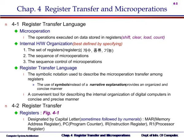
Register Transfer Language Registers (R) ALU (f) MICROOPERATION Digital systems are composed of modules that are constructed from digital components, such as registers, decoders, arithmetic elements, and control logic MICROOPERATION: An elementary operation performed during one clock pulse, on the information stored in one or more registers 1 clock cycle operation ex.: shift, count, clear, load, add,...
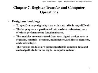
Register Transfer Language REGISTER TRANSFER LANGUAGE • The internal hardware organization of a digital computer is best defined by specifying : • The set of registers it contains and their functions • The sequence of microoperations performed on the binary information stored • The control that initiates the sequence of microoperations For any function of the computer, a sequence of microoperations is used to describe it ----> Register transfer language - A symbolic language - A convenient tool for describing the internal organization of digital computers - Can also be used to facilitate the design process of digital systems.
Register Transfer REGISTER TRANSFER - a register - portion of a register - a bit of a register Designation of a register Common ways of drawing the block diagram of a register Showing individual bits Register R1 7 6 5 4 3 2 1 0 15 15 8 7 0 0 R2 PC(H) PC(L) Numbering of bits Subfields Representation of a transfer(parallel) R2 R1 • This statement implies that the hardware is available • The outputs of the source must have a path to the inputs of the destination • The destination register has a parallel load capability P: R2 R1 Representation of a controlled(conditional) transfer A binary condition(p=1) which determines when the transfer is to occur If (p=1) then (R2 R1)
Register Transfer HARDWARE IMPLEMENTATION OF CONTROLLED TRANSFERS Implementation of controlled transfer P: R2 R1 Block diagram Load P Control Circuit R2 Clock n R1 Timing diagram t t+1 Clock Load Transfer occurs here A comma is used to separate two or more operations that are executed at the same time in one clock cycle
Questions • Show the block diagram of the hardware that implements the following register transfer statement: • yT2: R2R1, R1 R2 • Explain the memory operation in each case. • A. R2M[AR] • B. M[AR] R3
Bus and Memory Transfers Register A Register B Register C Register D Bus lines BUS AND MEMORY TRANSFER Bus is a path(of a group of wires) over which information is transferred, from any of several sources to any of several destinations. From a register to bus: BUS <- R Bus lines Load Reg. R0 Reg. R1 Reg. R2 Reg. R3 D D D D 0 1 2 3 z E (enable) Select 2 x 4 w Decoder
Bus and Memory Transfers MEMORY TRANSFERS Read Memory unit AR Write DR Memory read micro-op: DR M ( DR M[AR] ) Memory write micro-op: M DR ( M[AR] DR ) Summary of Register Transfer Microoperations A B Transfer content of reg. B into reg. A AR DR(N) Transfer content of N bits portion of reg. DR into reg. AR A constant Transfer a binary constant into reg. A ABUS R1, Transfer content of R1 into bus A and, at the same time, R2 ABUS transfer content of bus A into R2 AR Address register DR Data register M[AR] Memory word specified by reg. AR DR M[AR] Memory read operation: transfers content of memory word specified by AR into DR M[AR] DR Memory write operation: transfers content of DR into memory word specified by AR
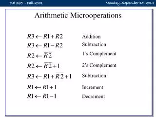
Arithmetic Microoperations ARITHMETIC MICROOPERATIONS Four types of microoperations - Register transfer microoperations - Arithmetic microoperations - Logic microoperations - Shift microoperations * Summary of Arithmetic Micro-Operations • R3 R1 + R2 Contents of R1 plus R2 transferred to R3 • R3 R1 - R2 Contents of R1 minus R2 transferred to R3 • R2 R2’ Complement the contents of R2 • R2 R2’+ 1 2's complement the contents of R2 (negate) • R3 R1 + R2’+ 1 subtraction • R1 R1 + 1 Increment • R1 R1 - 1 Decrement
Arithmetic Microoperations BINARY ADDER Binary Adder • • The subtraction A-B can be carried out by the following steps: • Take the 1’s complement of B (invert each bit) • Get the 2’s complement by adding 1 • Add the result to A Binary Adder-Subtractor
Question • Draw the block diagram for the hardware that Implements the following statement: • x+yz: AR AR + BR
Arithmetic Microoperations ARITHMETIC CIRCUIT Cin S1 S0 A0 X0 C0 D0 S1 FA S0 Y0 C1 4x1 B0 0 1 MUX 2 3 A1 X1 C1 D1 S1 FA S0 Y1 C2 B1 4x1 0 1 MUX 2 3 A2 X2 C2 S1 D2 FA S0 Y2 C3 4x1 B2 0 1 MUX 2 3 A3 X3 C3 D3 S1 FA S0 Y3 C4 4x1 B3 0 1 MUX 2 Cout 3 0 1
Question • The Arithmetic circuit in last slide has following values for S1, S0 and Cin. In each case determine the value of the output D in terms of the two input registers A and B. What is the corresponding microoperation? S1 S0 Cin Output Microoperation 0 0 0 0 0 1 0 1 0 0 1 1 1 0 0 1 0 1 1 1 0 1 1 1
Logic Microoperations HARDWARE IMPLEMENTATION OF LOGIC MICROOPERATIONS Question: Draw the digital circuit that performs the following logical operations between reg. A and reg. B(draw the circuit for one bit), then list the circuit function table: (AND, OR, XOR and Complement). 0
Answer A i 0 B i 1 4 X 1 F i MUX 2 3 Select S 1 S Function table -operation S1 S0 Output 0 0 F = A B AND 0 1 F = AB OR 1 0 F = A B XOR 1 1 F = A’ Complement
Shift Microoperations SHIFT MICROOPERATIONS Shifts - Logical shift : shift in a 0 into the extreme flip-flop - Circular shift : circulates the bits of the register around the two ends - Arithmetic shift : shifts a signed number (shift with sign extension) Left shift -> multiplied by 2 Right shift -> divided by 2 Arithmetic shifts for signed binary numbers - Arithmetic shift-right Sign bit Rn-1 Rn-2 R1 R0 - Arithmetic shift-left Overflow V = Rn-1 Rn-2 Shift Micro-Operations • Symbol Description • R shl R Shift-left register R • R shr R Shift-right register R • R cil R Circular shift-left register R • R cir R Circular right-shift register R • R ashl R Arithmetic shift-left register R • R ashr R Arithmetic shift-right register R
Question • An 8-bits register R ahs the following value: 11001010, find the value of R after performing the following shifts: • Logical shift left • Logical shift right • Circular shift left • Circular shift right • Arithmetic shift left • Arithmetic shift right
Shift Microoperations ARITHMETIC LOGIC SHIFT UNIT S3 S2 C i S1 S0 D Arithmetic i Circuit Select 4 x 1 0 F C i i+1 1 MUX 2 3 E Logic i B Circuit i A i shr A i-1 shl A i+1 • S3 S2 S1 S0 Cin Operation Function • 0 0 0 0 0 F = A Transfer A • 0 0 0 0 1 F = A + 1 Increment A • 0 0 0 1 0 F = A + B Addition • 0 0 0 1 1 F = A + B + 1 Add with carry • 0 0 1 0 0 F = A + B’ Subtract with borrow • 0 0 1 0 1 F = A + B’+ 1 Subtraction • 0 0 1 1 0 F = A - 1 Decrement A • 0 0 1 1 1 F = A TransferA • 0 1 0 0 X F = A B AND • 0 1 0 1 X F = A B OR • 0 1 1 0 X F = A B XOR • 0 1 1 1 X F = A’ Complement A • 1 0 X X X F = shr A Shift right A into F • 1 1 X X X F = shl A Shift left A into F