Download
1 / 43
430 likes | 774 Views
Chapter 7 EGR 272 – Circuit Theory II. 1. Welcome to EGR 272 Circuit Theory II. Syllabus Homework Web page Office hours EGR 271: Chapters 1 - 6 in Electric Circuits, 9 th Edition by Nilsson

E N D
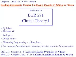
Chapter 7 EGR 272 – Circuit Theory II 1 Welcome to EGR 272 Circuit Theory II • Syllabus • Homework • Web page • Office hours • EGR 271: Chapters 1 - 6 in Electric Circuits, 9th Editionby Nilsson • EGR 272: Chapters 7-10, 12 - 15 in Electric Circuits, 9th Editionby Nilsson
Chapter 7 EGR 272 – Circuit Theory II 2 Sequence of Electrical/Computer Engineering Courses at TCC EGR 271 (3 cr) Circuit Theory I ODU equiv: ECE 201 Offered: F, Sp, Su MTH 279 (4 cr) Differential Equations EGR 125 (4 cr) Into to Engineering Methods (C++) EGR 272 (3 cr) Circuit Theory II ODU equiv: ECE 202 Offered: F, Sp EGR 262 (2 cr) Fund. Circuits Lab ODU equiv: ECE 287 Offered: F, Sp, Su EGR 270 (4 cr) Fund. Of Computer EGR ODU equiv: ECE 241 Offered: F, Sp, Su Notes: Classes available at the Virginia Beach Campus, the Chesapeake Campus, and the Tri-Cities Center EGR 271-272 transfers to Virginia Tech as ECE 2004 EGR 270 transfers to Virginia Tech as ECE 2504 EGR 262 does not transfer to Virginia Tech
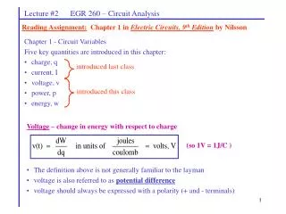
Chapter 7 EGR 272 – Circuit Theory II 3 Reading Assignment:Chapter 7 in Electric Circuits, 9th Ed.by Nilsson Chapter 7 – Circuit Analysis with Capacitors and Inductors KVL and KCL involving circuits with capacitors and inductors result in differential equations (D.E.) rather than algebraic equations. The order of a differential equation is equal to highest derivative.
Chapter 7 EGR 272 – Circuit Theory II 4 Order of a circuit Order of the differential equation (DE) required to describe the circuit The number of independent* energy storage elements (C’s and L’s) = = Circuit Order * C’s and L’s are independent if they cannot be combined with other C’s and L’s (in series or parallel, for example) Examples:Draw several circuits with inductors and capacitors and determine the order of each circuit.
5 • First-Order Circuits • A first-order circuit can only contain one energy storage element (a capacitor or an inductor). The circuit will also contain resistance (discuss). So there are two types of first-order circuits: • RC circuit • RL circuit Source-Free Circuits A source-free circuit is one where all independent sources have been disconnected from the circuit after some switch action. The voltages and currents in the circuit typically will have some transient response due to initial conditions (initial capacitor voltages and initial inductor currents). We will begin by analyzing source-free circuits as they are the simplest type. Later we will analyze circuits that also contain sources after the initial switch action.
Chapter 7 EGR 272 – Circuit Theory II 6 Source-free RC circuit Consider the RC circuit shown below. Note that it is source-free because no sources are connected to the circuit for t > 0. Use KCL to find the differential equation: and solve the differential equation to show that:
Chapter 7 EGR 272 – Circuit Theory II 7 • Checks on the solution • Verify that the initial condition is satisfied. • Find dv(t)/dt and regenerate the D.E. from the solution. • Show that the energy dissipated over all time by the resistor equals the initial energy stored in the capacitor.
Chapter 7 EGR 272 – Circuit Theory II 8 General form of the D.E. and the response for a 1st-order source-free circuit In general, a first-order D.E. has the form: Solving this differential equation (as we did with the RC circuit) yields: where = (Greek letter “Tau”) = time constant (in seconds) Notes concerning : 1) for the previous RC circuit the DE was: so (for an RC circuit) = RC
Chapter 7 EGR 272 – Circuit Theory II 9 Smaller t (faster decay) x(0) Larger t (slower decay) t 0 0 2) is related to the rate of exponential decay in a circuit as shown below 3) It is typically easier to sketch a response in terms of multiples of than to be concerning with scaling of the graph (otherwise choosing an appropriate scale can be difficult). This is illustrated on the following page.
Chapter 7 EGR 272 – Circuit Theory II 10 x(t) t 0 t 2t 3t 4t 5t Graphing functions in terms of : Illustration: A) Calculate values for x(t) = x(0)e-t/ for t = , 2, 3, 4, and 5. B) Graph x(t) versus t for t = 0, , 2, 3, 4, and 5.
Chapter 7 EGR 272 – Circuit Theory II 11 t = tx t = tx Circuit 470uF Rbleeder Time for a circuit to completely decay From the last page note that x(5t) = x(0)e-5t/ = x(0)e-5 = 0.007x(0) This means that magnitude of x(t) is only 0.7% of its initial value by time 5 (or the function has lost 99.3% of its original value). Technically a decaying exponential function never reaches zero, but we see that by time t = 5 it is very close. So we generally use the approximation that: 5 = time for a circuit to decay Example: Some circuits connect a “bleeder resistor” in parallel with a capacitor when the circuit is turned off in order to safely discharge the capacitor (which might otherwise have a significant voltage across it for a long time). For the circuit shown below, what value of Rbleeder should be used in order to discharge the capacitor in 10 seconds (the circuit is turned off at time t = tx)?
Chapter 7 EGR 272 – Circuit Theory II 12 Example: The switch in the circuit shown had been closed for a long time and then opened at time t = 0. A) Determine an expression for v(t). B) Graph v(t) versus t.
Chapter 7 EGR 272 – Circuit Theory II 13 Example: (continued) C) How long will it take for the capacitor to completely discharge? D) Determine the capacitor voltage at time t = 100 ms. E) Determine the time at which the capacitor voltage is 10V.
Chapter 7 EGR 272 – Circuit Theory II 14 Circuit t > 0 independent sources killed REQ Circuit C Equivalent Resistance seen by a Capacitor For the RC circuit in the previous example, it was determined that = RC. But what value of R should be used in circuits with multiple resistors? In general, a first-order RC circuit has the following time constant: = REQ C where Req is the Thevenin resistance seen by the capacitor. More specifically,
Chapter 7 EGR 272 – Circuit Theory II 15 Example: Determine an expression for v(t). Graph v(t) versus t.
Chapter 7 EGR 272 – Circuit Theory II 16 Source-free RL circuit Consider the RL circuit shown below. Use KVL to find the differential equation: and use the general form of the solution to a first-order D.E. to show that: = L/R
Chapter 7 EGR 272 – Circuit Theory II 17 Circuit t > 0 independent sources killed REQ Circuit L Equivalent Resistance seen by an Inductor For the RL circuit in the previous example, it was determined that = L/R. As with the RC circuit, the value of R should actually be the equivalent (or Thevenin) resistance seen by the inductor. In general, a first-order RL circuit has the following time constant: where
Chapter 7 EGR 272 – Circuit Theory II 18 Example: Determine an expression for i(t). Sketch i(t) versus t.
Chapter 7 EGR 272 – Circuit Theory II 19 First-order circuits with DC forcing functions: In the last class we consider source-free circuits (circuits with no independent sources for t > ). Now we will consider circuits having DC forcing functions for t > 0 (i.e., circuits that do have independent DC sources for t > 0). The general solution to a differential equation has two parts: x(t) = xh + xp = homogeneous solution + particular solution orx(t) = xn + xf = natural solution + forced solution where xh or xn is due to the initial conditions in the circuit and xp or xf is due to the forcing functions (independent voltage and current sources for t > 0). xp or xf in general take on the “form” of the forcing functions, so DC sources imply that the forced response function will be a constant (DC), sinusoidal sources imply that the forced response will be sinusoidal, etc. Since we are only considering DC forcing functions in this chapter, we assume that xf = B (a constant)
Chapter 7 EGR 272 – Circuit Theory II 20 Recall that a 1st-order source-free circuit had the form Ae-t/ . Note that there was a natural response only since there were no forcing functions (sources) for t > 0. So the natural response was xn = Ae-t/ The complete response for 1st-order circuit with DC forcing functions therefore will have the form x(t) = xf + xn or x(t) = B + Ae-t/ The “Shortcut Method” An easy way to find the constants B and A is to evaluate x(t) at 2 points. Two convenient points at t = 0- and t = since the circuit is in steady-state at these two points. This approach is sometimes called the “shortcut method.” So, x(0) = B + Ae0 = B + A And x() = B + Ae- = B Show how this yields the following expression found in the text: x(t) = x() +[x(0) - x()]e-t/
Chapter 7 EGR 272 – Circuit Theory II 21 “Shortcut Method” - Procedure The shortcut method will be the key method used in this chapter to analyze 1st-order circuit with DC forcing functions: 1) Analyze the circuit at t = 0-: Find x(0-) = x(0+), where x = vC or iL . 2) Analyze the circuit at t = : Find x(). 3) Find = REQC or = L/REQ . 4) Assume that x(t) has the form x(t) = B + Ae-t/ and solve for B and A using x(0) and x(). • Notes: • The “shortcut method” also works for source-free circuits, but x() = B = 0 since the circuit is dead at t = . • If variables other than vC or iL are needed, it is generally easiest to solve for vC or iL first and then use the result to find the desired variable.
Chapter 7 EGR 272 – Circuit Theory II 22 Example: Find v(t) and i(t) for t > 0.
Chapter 7 EGR 272 – Circuit Theory II 23 Example: Find v(t) and i(t) for t > 0.
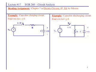
Chapter 7 EGR 272 – Circuit Theory II 24 Charging and discharging capacitors – the forms of these two simple circuits are commonly referred to in later courses. Example: Capacitor charging circuit. Find v(t) for t > 0. Example: Capacitor discharging circuit. Find v(t) for t > 0.
Chapter 7 EGR 272 – Circuit Theory II 25 1st-order Circuits with Dependent Sources Dependent sources affect the resistance seen by the inductor or capacitor and therefore affect the value of for the circuit. Two approaches can be used to find : 1) When REQ seen by an inductor or a capacitor, remove the L or C, kill any independent sources, and place any value independent source at the terminals. Then 2) Write a DE for the circuit (any variable) and can be easily determined from the DE since it has the form:
Chapter 7 EGR 272 – Circuit Theory II 26 Example: Find v(t) for t > 0 if v(0) = 2 V. A) Use method 1: Find t = REQC using
Chapter 7 EGR 272 – Circuit Theory II 27 Example: (continued) Find v(t) for t > 0 if v(0) = 2 V. B) Use method 2: Write a DE for v(t).
Chapter 7 EGR 272 – Circuit Theory II 28 • Unit Step Functions • Unit step functions have several important uses in electrical engineering, including: • representing piecewise-continuous signals • representing switches • defining functions for use with one-sided Laplace transforms (in EGR 261) Definition: u(t) = unit step function where and u(t) is represented by the graph shown below.
Chapter 7 EGR 272 – Circuit Theory II 29 • A good way to think of a unit step function is as follows: • u(argument) = 1 for argument > 0 • u(argument) = 0 for argument < 0 • the transition in u(argument) occurs where argument = 0 Example: Graph 4u(t - 2) u(argument) = 0 for argument < 0. Note that for t < 2, u(t - 2) has a negative argument. For example, when t = 1, u(t - 2) = u(1 - 2) = u(-1) = 0. u(argument) = 1 for argument > 0. Note that for t > 2, u(t - 2) has a positive argument. For example, when t = 3, u(t - 2) = u(3 - 2) = u(+1) = 1. The transition occurs when the argument = 0. Note that when t = 2, u(t - 2) = u(2 - 2) = u(0).
Chapter 7 EGR 272 – Circuit Theory II 30 • Example: Graph the following functions: • 1) -2u(t - 10) • 2) 3u(t + 2) • 4u(-t) • 4) 4u(2-t)
Chapter 7 EGR 272 – Circuit Theory II 31 Example: Graph the following functions (continued): 5) 6u(-4-t) 6) u(-t) 7) Show that 1 - u(t) = u(-t) 8) sin(t) and sin(t)u(t)
Chapter 7 EGR 272 – Circuit Theory II 32 Example: Graph the following functions (continued): 9) u(t) - u(t - 2) 10) f(t) = 2t 11) 2t[u(t) - u(t - 2)] - discuss the concept of a “window”
Chapter 7 EGR 272 – Circuit Theory II 33 Example: Graph the following functions (continued): 12) f(t)[u(t - 2) - u(t - 4)] for any f(t) 13) (2t + 6)[u(t + 2) - u(t - 2)]
Chapter 7 EGR 272 – Circuit Theory II 34 • There are two common types of problems in representing functions using unit step functions: • 1) Determining the function that represents a given graph • Approach: Represent each unique portion of the function using unit step “windows” • 2) Graphing a function specified by unit steps • Approach: As each unit step function “turns on”, graph the cumulative function.
Chapter 7 EGR 272 – Circuit Theory II 35 • Determining the function that represents a given graph: • Approach: Represent each unique portion of the function using unit step “windows” Example:
Chapter 7 EGR 272 – Circuit Theory II 36 Example:
Chapter 7 EGR 272 – Circuit Theory II 37 • Graphing a function specified using unit steps functions: • Approach: As each unit step function “turns on”, graph the cumulativefunction (i.e., add each part as it turns on). Example: Graph f(t) = 2u(t) + 4u(t – 2) – 8u(t – 4) Solution: f(t) = 2u(t) + 4u(t – 2) – 8u(t – 4) turns ON at t = 0 turns ON at t = 2 turns ON at t = 4 f(t) 6 2 t 4 2 -2
Chapter 7 EGR 272 – Circuit Theory II 38 2) Graph f(t) = (t + 2)u(t + 1) + (3 – t)u(t – 2) - (2t-5)u(t – 4) 3) Graph f(t) = 4sin(4t)[u(t) – u(t – 1)]
Chapter 7 EGR 272 – Circuit Theory II 39 Using unit step functions to replace switches in circuits Unit step functions are commonly used to represent switches in circuits. Consider the following examples. • Example: A unit step function is used below to replace a switch connecting a voltage source. • Discuss the value of VX. • Discuss the forms of the solution.
Chapter 7 EGR 272 – Circuit Theory II 40 • Example: A unit step function can be used to replace a switch disconnecting a current source. • Discuss the concept of a “make before break” switch • Discuss the value of IX. • Draw two possible circuits using unit step functions that are equivalent to the • circuit shown below.
Chapter 7 EGR 272 – Circuit Theory II 41 Example: Determine an expression for v(t) in the circuit below. Use the “shortcut method.”
Chapter 7 EGR 272 – Circuit Theory II 42 Circuit with zero initial conditions Input is 1u(t) V or 1u(t) A Output (a voltage or a current) is the “unit step response” Unit step response to a circuit Suppose that you wished to compare the outputs of two circuits. It would be misleading to compare them if the circuits had different inputs or different initial conditions. A common way to compare them is to use a unit step input [1u(t)V or 1u(t)A] and zero initial conditions (or zero initial stored energy). Unit step response – the output of a circuit where the input is a unit step and there are zero initial conditions.
Chapter 7 EGR 272 – Circuit Theory II 43 Example:Find the unit step response for VC(t) in the circuit shown below.