Download
1 / 16
160 likes | 442 Views
Lecture #12 EGR 260 – Circuit Analysis. Reading Assignment: Sections 4.9 - 4.16 in Electric Circuits, 9 th Ed. by Nilsson. Thevenin’s & Norton’s Theorems

E N D
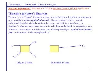
Lecture #12 EGR 260 – Circuit Analysis Reading Assignment:Sections 4.9 - 4.16 in Electric Circuits, 9th Ed. by Nilsson Thevenin’s & Norton’s Theorems Thevenin’s and Norton’s theorems are two related theorems that allow us to represent any circuit by a simple equivalent circuit. The equivalent circuit is easier to understand than the original circuit and gives us insight into circuit behavior. Engineer’s often use equivalent systems to help them understand the original system. In Statics, for example, multiple forces are often replaced by an equivalent resultant force, as illustrated in the example below. F1 FR F3 F2 F4 Original System Equivalent System
Lecture #12 EGR 260 – Circuit Analysis Thevenin’s & Norton’s Theorems Any one-port network N may be represented by either of the following types of equivalent circuits: Thevenin Equivalent Circuit (TEC) – consisting of a voltage source and a series impedance Norton Equivalent Circuit (NEC) – consisting of a current source and a parallel impedance where
+ Network N Network N VOC Load _ ISC Network N Network N Load Lecture #12 EGR 260 – Circuit Analysis Illustration of VOC and ISC: Remove the load and the voltage across the open terminals is VOC Replace the load by a short circuit (wire) and the current through the short is ISC
Lecture #12 EGR 260 – Circuit Analysis There are 3 ways to find the TEC or NEC for a given circuit: Examples using each of the three methods will be provided on the following pages.
Lecture #12 EGR 260 – Circuit Analysis Example: Find the TEC and the NEC seen by R in the circuit shown below. Discuss which method to use.
Lecture #12 EGR 260 – Circuit Analysis Example: Find the TEC seen by R in the circuit shown below. Discuss which method to use.
Lecture #12 EGR 260 – Circuit Analysis Example: Find VL for R = 10, 20, 40, and 80 ohms in the circuit shown below. Hint: Use the TEC instead of the original circuit.
Lecture #12 EGR 260 – Circuit Analysis Example: Find the TEC seen by R in the circuit shown below. Discuss which method to use.
Lecture #12 EGR 260 – Circuit Analysis Finding Thevenin resistance by adding external sources As indicated in Method 2 for finding a TEC or NEC, RTH can also be found as follows: Discussion: If the dead circuit really acts like a resistor (RTH), then we can add any voltage source across the circuit (resistor), solve for the current, and use Ohm’s Law to find RTH. Similarly, we can add any value current source and solve for the voltage. This technique is illustrated below. Case 1: Add an external voltage source Case 2: Add an external current source IT Dead Circuit (independent sources killed) Dead Circuit (independent sources killed) + + _ VT 10V = VT 2A = IT _ Add any value of voltage source and solve for IT Add any value of current source and solve for VT
Lecture #12 EGR 260 – Circuit Analysis Example: Find the RTH seen by R in the circuit shown below using Method 2 (i.e., add an external source). Compare the results to the value found previously using Method 3.
Lecture #12 EGR 260 – Circuit Analysis Maximum Power Transfer Theorem Suppose that a general network N has a resistive load as shown below. • Now we might consider two questions: • For what value of RL is maximum power delivered to RL? • What is the maximum power that can be delivered to RL? To answer these questions (see next page), 1) Replace N by a Thevenin Equivalent Circuit 2) Determine a general expression for power to RL 3)
Lecture #12 EGR 260 – Circuit Analysis Maximum Power Transfer Theorem Show that:
Lecture #12 EGR 260 – Circuit Analysis The relationship between PL and RL can be illustrated by the graph shown below.
Lecture #12 EGR 260 – Circuit Analysis Example: A) For what value of R in the circuit below is maximum power delivered to R? B) Determine the maximum power that could be delivered to R.
Lecture #12 EGR 260 – Circuit Analysis Example: C) Determine the power delivered to R when R = 20, 50, 100, 200, 400, 800, and 2000 ohms. D) Plot PL versus R.
30 60 20 + 100 V _ 60 R Lecture #12 EGR 260 – Circuit Analysis Example: Find R such that maximum power is delivered to R. Also find Pmax. (Recall that this circuit was used in an earlier example.)


