Download
1 / 20
200 likes | 370 Views
Chapter 1 - Circuit Variables Five key quantities are introduced in this chapter: charge, q current, I voltage, v power, p energy, w . introduced last class. introduced this class. Lecture #2 EGR 260 – Circuit Analysis.

E N D
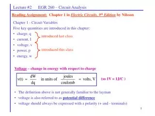
Chapter 1 - Circuit Variables • Five key quantities are introduced in this chapter: • charge, q • current, I • voltage, v • power, p • energy, w introduced last class introduced this class Lecture #2 EGR 260 – Circuit Analysis Reading Assignment: Chapter 1 in Electric Circuits, 9th Edition by Nilsson Voltage – change in energy with respect to charge (so 1V = 1J/C ) • The definition above is not generally familiar to the layman • voltage is also referred to as potential difference • voltage should always be expressed with a polarity (+ and - terminals)
electrons enter the device at a higher energy level 1C + - + 1J of energy is used (stored or given off as heat or light) 12V -12V 12V Element 1V - + _ electrons leave the device at a lower energy level Unclear Two equivalent representations of the voltage across a circuit element 1C Lecture #2 EGR 260 – Circuit Analysis Polarity: voltage should always be expressed with a polarity (+ and - terminals) If 1V = 1 J/C, then 1V of potential difference exists across an element if 1J of energy is expended in passing 1C of charge though the element as illustrated below:
Lecture #2 EGR 260 – Circuit Analysis Voltage is sometimes referred to as an “electrical pressure” which forces charge through a circuit. Water pipe analogy: Sometimes an analogy is made between an electric circuit and a water system. This may help to give a more intuitive feel to terms like charge, current, and voltage.
_ + V I Passive Device Passive Device Lecture #2 EGR 260 – Circuit Analysis Passive and Active Devices Passive device – a device that dissipates (uses) energy. The energy is given off as heat or light. Examples of passive devices: resistors, inductors, and capacitors (to be introduced later). Practical items like filaments in bulbs, burners on a stove, etc., are essentially resistors so they are also passive devices. The burner on your stove can only use energy - it can’t produce energy on its own. Passive sign convention – current is shown entering the positive terminal. Therefore, if the current direction is known, then the voltage polarity is known, and vice versa. The voltage polarity is known from the current direction or the current direction is known from the voltage polarity
_ V + I = 2A R = 10 Lecture #2 EGR 260 – Circuit Analysis Ohm’s Law will be introduced in Chapter 2, but here it will be used briefly to make a point about passive sign convention. Ohm’s Law: V = IR (voltage = current x resistance) This law describes how voltage and current are related for a resistor. Since a resistor is a passive device, this formula requires that passive sign convention be used. Example: Calculate the voltage, V, across the resistor shown below.
Lecture #2 EGR 260 – Circuit Analysis Active device – a device that is capable of delivering (supplying) energy, but might use energy, such as when a battery is being charged. Examples of active devices: batteries, voltage sources, and current sources (to be introduced later) Active sign convention – current is shown leaving the positive terminal. Therefore, if the current direction is known, then the voltage polarity is known, and vice versa. Examples: Show examples of active-sign convention used with batteries and voltage sources
Lecture #2 EGR 260 – Circuit Analysis Power – the rate of change of energy with respect to time (So 1 W = 1 J/s) also (So 1 W = 1 V·A) • Notes: • If voltage and current are shown using passive sign convention then p = vi calculates power absorbed (or used or dissipated) • If voltage and current are shown using active sign convention then p = vi calculates power delivered (or generated or supplied) • Power delivered = -(Power absorbed) • Whenever power is calculated, it should be made clear whether it is absorbed or delivered
Case 1: _ + 15 V 2A Case 2: _ + 15 V -2A Case 3: _ 15 V + 2A Case 4: _ 15 V + -2A Lecture #2 EGR 260 – Circuit Analysis Example: Find the power in each case shown below.
10A + 12V - Good car battery - 12V + Weak car battery Lecture #2 EGR 260 – Circuit Analysis Example: Shown below is an illustration of using one car battery to “jump start” another car battery. Calculate the power for each battery. Power check: For any circuit the following relationship exists: Pdel = Pabs
Lecture #2 EGR 260 – Circuit Analysis Example: (Problem 1-28 in Electric Circuits, 7th Edition, by Nilsson) The numerical values for the currents and voltages in the circuit shown are given in the table below. Find the total power developed in the circuit. Show that Pdel = Pabs.
Lecture #2 EGR 260 – Circuit Analysis Energy: W or w(t) = energy (in joules, where 1J = 1Ws ) or Example: Given p(t) below, find the energy at time t = 3 seconds
i(t) + 6V - Lecture #2 EGR 260 – Circuit Analysis Example:If i(t) is the current entering the device shown below, sketch p(t) and w(t).
Lecture #2 EGR 260 – Circuit Analysis Energy Cost Virginia Power charges for the amount of energy that is used each month (power is the rate at which the energy is used). The unit of energy used on power bills is the kilowatt-hour, kWh. 1 kWh = (1000W)(3600 s) = 3600000 Ws = 3.6 MJ A typical rate used for energy costs might be 8¢/ kWh (discuss) If energy is used linearly, then Typical power rates for appliances:
Lecture #2 EGR 260 – Circuit Analysis Example: Calculate the monthly cost to keep a porch light on each night.
Lecture #2 EGR 260 – Circuit Analysis Reading Assignment: Chapter 2 in Electric Circuits, 7th Edition by Nilsson Chapter 2: Electrical Devices Several types of electrical devices are introduced in this chapter, including independent sources, dependent sources, and resistors. Independent sources – 2 types: 1) Independent voltage source 2) Independent current source
Long bar represents positive terminal Battery General Sinusoidal Voltage Voltage Source Source (e.g., 10sin(120t) V) 2A 100A 20A Circuit 1 Circuit 3 Circuit 2 12V 12V 12V Lecture #2 EGR 260 – Circuit Analysis Independent voltage source – a device which maintains its specified voltage for any load current that is required. Symbols: Note: The symbols shown above are from PSPICE. The boxes on the ends of the wires are simply for connecting wires or other components to the sources. Voltages sources have a specified voltage, but the current depends on the circuit and is determined through analysis. Example: The current provided by the 12V source below varies in each case.
Lecture #2 EGR 260 – Circuit Analysis Independent voltage source characteristics The “characteristics” of a device typically refers to a graph of I versus V which illustrates the behavior of the device. The characteristics of an ideal independent 12 V voltage source are shown below. I Current can have any value (depends on the circuit) V 12V Voltage is fixed at 12V
Lecture #2 EGR 260 – Circuit Analysis • Real versus ideal independent voltage sources • The voltage delivered by an real voltage source (or practical voltage source) will typically drop as the current required by the source increases. For example: • The 1.5V across a D-cell in a flashlight drops when the light is turned on. • The 12V across a car battery drops when the car is started. • The voltage from a power company drops during peak load hours (the voltage typically ranges from 115V - 130V). • Example: I Ideal 12V voltage source Real 12V voltage source V 12V Note: Any voltage source shown in the text is assumed to be ideal.
+ + + Circuit 2 Circuit 3 Circuit 1 75V 200V 10V 2A 2A 2A _ _ _ Lecture #2 EGR 260 – Circuit Analysis Independent current source – a device which maintains its specified current for any load voltage that is required. (This device is not as common in everyday use as the independent voltage source.) Symbol: Note: The symbol shown above is from PSPICE. The boxes on the ends of the wires are simply for connecting wires or other components to the source. Current sources have a specified current, but the voltage depends on the circuit and is determined through analysis. Example: The voltage provided by the 2A source below varies in each case.
I 2A Current is fixed at 2A V I Ideal 2A current source 2A Real 2A current source V Lecture #2 EGR 260 – Circuit Analysis Independent current source characteristics The characteristics of an ideal independent 2A current source are shown below. Voltage can have any value (depends on the circuit) Real versus ideal independent current sources The current delivered by an real current source (or practical current source) will typically drop as the voltage required by the source increases. Example: Note: Any current source shown in the text is assumed to be ideal.


