LDA Protoype Board
50 likes | 155 Views
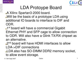
A Xilinx Spartan3-2000 board. Will be the basis of a prototype LDA using additional IO boards to interface to DIF and ODR. 1 st board will have a commercial Gigabit Ethernet PHY and SFP cage to allow connection to ODR. Will also have a Glink TX/RX chipset as an alternative.

LDA Protoype Board
E N D
Presentation Transcript
A Xilinx Spartan3-2000 board. Will be the basis of a prototype LDA using additional IO boards to interface to DIF and ODR. 1st board will have a commercial Gigabit Ethernet PHY and SFP cage to allow connection to ODR. Will also have a Glink TX/RX chipset as an alternative. 2nd board will have HDMI interfaces to allow LDA->DIF connections LDA also has SO-DIMM DDR2 memory socket, to allow event storage. LDA Protoype Board Calice
Calice Broaddown 2 board from Enterpoint Ltd.
Calice Front SO-DIMM RAM Used to buffer Event data IO Bank HDMI interface board will be attached here for LDA->DIF Connections IO Bank Can be used for diagnostics and general IO PCI Connector Used as generic IO with adaptor. Feed in machine clock + timing signals
Calice Back High Density back connector. Gigabit Ethernet and GLink interface add-on board will be here.
Calice • DIF<->LDA connection is a serial link, sent via HDMI cables. Cables are capable of many hundreds MHz rates easily. • Anticipating between 8 and 16 HDMI links on the LDA. • Expected initial usage rates are ~200MHz. • FPGA on LDA and DIF will do the SerDes work, using the reference clock sent over the HDMI cable. It is expected to be some multiple of the machine clock. • Initial VHDL work done using 8B/10B encoding, a simple parallel to serial and serial to parallel module tested in a VHDL test bench Need to be tested on real hardware next. • LDA<->DIF connection is via Ethernet link, either a commercial IP MAC layer can be used, or there is a fully working 10/100/1000 MAC available on www.opencores.org. • The Glink chipset is also a possible connection, maybe for diagnostics or as an alternative to the Ethernet. • Both add-on boards will be produced by the same company who make the main board, and the final specification for these will be submitted ASAP.