MAC Performance Analysis for Vehicle to Infrastructure Communication
150 likes | 330 Views
MAC Performance Analysis for Vehicle to Infrastructure Communication. Tom H. Luan*, Xinhua Ling , Xuemin (Sherman) Shen* *BroadBand Communication Research Group University of Waterloo. §. Research In Motion. §. Outline. Introduction to Vehicular Network Model of MAC in V2I communication

MAC Performance Analysis for Vehicle to Infrastructure Communication
E N D
Presentation Transcript
MAC Performance Analysis for Vehicle to Infrastructure Communication Tom H. Luan*, Xinhua Ling , Xuemin (Sherman) Shen* *BroadBand Communication Research Group University of Waterloo § Research In Motion §
Outline • Introduction to Vehicular Network • Model of MAC in V2I communication • Simulation • Conclusion
Why Vehicular Networks ? • Internet becomes an essential part of our daily life • Watch video on Youtube; order literature on Amzone; catch the final moments of an eBay auction … • Americans spend up to 540 hours on average a year in their vehicles (10% of the waking time) • Internet access from vehicles is still luxury • Vehicular Network • To provide cheap yet high throughput data service for vehicles on the road
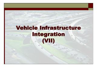
V2V and V2I Communications Vehicle to RSU (V2R or V2I) • Infotainment: Internet access, video streaming, music download, etc. • MAC throughput performance evaluation of V2I communication Vehicle to Vehicle (V2V) RSU (roadside unit)
Standard and Research Efforts • IEEE drafts 802.11p standard to permit vehicular communication • 802.11a radio technology + 802.11e EDCA MAC • Multi-channel: 6 service channels + 1 control channel • Drive-thru Internet • Using off-the-shelf 802.11b hardware, a vehicle could maintain a connection to a roadside AP for 500m and transfer 9MB of data at 80km/h using either TCP or UDP Image from http://www.drive-thru-internet.org/ [1] J. Ott and D. Kutscher, "Drive-thru Internet: IEEE 802.11 b for 'automobile' users," in IEEE INFOCOM, 2004
Standard and Research Efforts (cont’d) • CarTel in MIT [2] • City-wide experiment showing the intermittent and short-lived connectivity, yet high throughput while available • Small scale network without considering MAC • Link layer and transport layer performance • What if a great number of vehicles moving fast? [2] V. Bychkovsky, B. Hull, A. Miu, H. Balakrishnan and S. Madden, "A measurement study of vehicular internet access using in situ Wi-Fi networks," in ACM MobiCom, 2006
Problem Statement • MAC performance evaluation for fast-movinglarge scale vehicular networks • We consider 802.11b DCF • Used by most trail networks, e.g., Drive-thru • Compatible to WiFi device (e.g., iPod Touch) • The basis of 802.11p MAC
Network Model • Perfect channel without packet loss and errors • Saturated case: nodes always have a packet to transmit • Multi-rate transmission according to the distance to RSU • Spatial zones: the radio coverage of one RSU is divide into Z = {0, 1, …, N} zones according to node transmission rate • p-persistent MAC: nodes transmit with a constant probability pz for different zone n in Z • Mobility Model • Sojourn time of vehicles in each zone n is geometrically distributed with mean tn • Within a period , vehicle moves from zone n to n+1 with the probability /tn, and no change with the left probability
Markov Model of Vehicle Nodes • 2D Markov chain embedded at the commencement of the backoff counter countdown • Upon the decrement of backoff counter, vehicle may either move to the next zone or stay in the original zone • When coming into a new zone, different transmission probability is applied • Each node can be represented by {z(t), b(t)} • z(t): zone the vehicle is current in at time t • b(t): the value of backoff counter of the node at time t
Simulation Setup • Radio coverage of RSU is 250m, which is divided into 8 zones • By default, 50 vehicles move at constant speed with v = 80 km/h • When arriving at the end of the road session (zone N), vehicles reenter zone 0 and start a new iteration of communication • Two schemes • Equal contention window (transmission probability p) in all zones • Differential contention window in zones
Nodal Throughput in Each Zone n sn = Nodal Throughput in Each Zone Average pkt length in each trans. Mean interval between consecutive trans. Integrated Throughput Xnsn S = ∑ n Where Xn is the node population in zone n • Using equal CW in all zones would suffer from performance anomaly
Increasing Velocity • With enhanced node velocity, nodes in front zones have higher throughput than the back zones • The small CW in zone 4 benefits the following zones • System throughput reduces when velocity increases
Conclusion • Throughput performance evaluation of DCF in the vehicle to infrastructure communication • Increase the velocity would reduce the system throughput • Future work • Optimal design of DCF (contention window) • QoS provision with call admission control etc.
Question and Answers ? Thank you ! bbcr.uwaterloo.ca/~hluan