Download

1 / 37
370 likes | 564 Views
Unit 9 Multiplexers, Decoders, and Programmable Logic Devices. Ku-Yaw Chang canseco@mail.dyu.edu.tw Assistant Professor, Department of Computer Science and Information Engineering Da-Yeh University. Contents. 9.1 Introduction 9.2 Multiplexers 9.3 Three-State Buffers

E N D
Unit 9Multiplexers, Decoders, and Programmable Logic Devices Ku-Yaw Chang canseco@mail.dyu.edu.tw Assistant Professor, Department of Computer Science and Information Engineering Da-Yeh University
Contents 9.1 Introduction 9.2 Multiplexers 9.3 Three-State Buffers 9.4 Decoders and Encoders 9.5 Read-Only Memories 9.6 Programmable Logic Devices 9.7 Complex Programmable Logic Devices 9.8 Field Programmable Gate Arrays Fundamentals of Logic Design
Buffer • A gate output • Be connected to a limited number of other device inputs without degrading the performance • A simple buffer • Increase the driving capability of a gate input Fundamentals of Logic Design
Add Buffer • No bubble • F = C Fundamentals of Logic Design
Three-State Buffers • A logic gate will not operate correctly if the outputs of two or more gates or other logic devices are directly connected to each other. • In some cases, damage to the gates may result. Fundamentals of Logic Design
Three-State Buffers • Also called tri-state buffers • B = 1 • The output C equals A • B = 0 • The output C acts like an open circuit • A Hi-Z (high-impedance) Fundamentals of Logic Design
Four Types • The symbol Z represents the high-impedance state. Fundamentals of Logic Design
Data Selection • The outputs of two three-state buffers are tied together. • B = 0 • D = A • B = 1 • D = C • D = B’A + BC • Logically equivalent to using a 2-to-1 multiplexer Fundamentals of Logic Design
Two Three-State Buffers • Connect two three-state buffer outputs together Fundamentals of Logic Design
Four Sources Fundamentals of Logic Design
Bi-Directional Input/Output Pin Fundamentals of Logic Design
Contents 9.1 Introduction 9.2 Multiplexers 9.3 Three-State Buffers 9.4 Decoders and Encoders 9.5 Read-Only Memories 9.6 Programmable Logic Devices 9.7 Complex Programmable Logic Devices 9.8 Field Programmable Gate Arrays Fundamentals of Logic Design
3-to-8 Line Decoder • Exactly one of the output lines will be 1 for each combination of the values of the input variables. Fundamentals of Logic Design
4-to-10 Line Decoder Fundamentals of Logic Design
4-to-10 Line Decoder Fundamentals of Logic Design
Decoder • In general, an n-to-2n line decoder generate all 2n minterms (or maxterms) of the n input variables. • The outputs are defined as follows: • yi=mi , i =0 to 2n-1 (noninverted outputs) • yi=mi’ = Mi , i=0 to 2n-1 (inverted outputs) Fundamentals of Logic Design
Decoder • n-variable functions • be realized by ORing together selected minterm outputs from a decoder • outputs are inverted • Use NAND gates Fundamentals of Logic Design
Realization of a Multiple-Output Circuit Using a Decoder • f1(a,b,c,d) = m1 + m2 + m4 • f1 = (m1’m2’m4’)’ • f2(a,b,c,d) = m4 + m7 + m9 • f2 = (m4’m7’m9’)’ Fundamentals of Logic Design
Realization of a Multiple-Output Circuit Using a Decoder Fundamentals of Logic Design
Encoder • Perform the inverse function of a decoder Fundamentals of Logic Design
8-to-3 Priority Encoder Fundamentals of Logic Design
Contents 9.1 Introduction 9.2 Multiplexers 9.3 Three-State Buffers 9.4 Decoders and Encoders 9.5 Read-Only Memories 9.6 Programmable Logic Devices 9.7 Complex Programmable Logic Devices 9.8 Field Programmable Gate Arrays Fundamentals of Logic Design
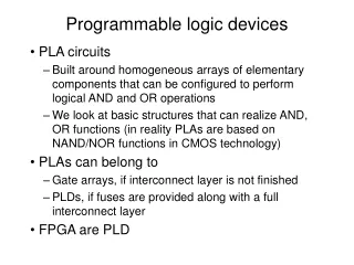
ROM • Read-Only Memories • An array of semiconductor devices that are interconnected to store an array of binary data • Can be read out whenever desired • Cannot be changed under normal operation conditions Fundamentals of Logic Design
ROM • ABC = 010 • F0F1F2F3 = 0111 • Word • Address Fundamentals of Logic Design
ROM • n input lines and m output lines • 2n words • Each word is m bits long Fundamentals of Logic Design
ROM • A 2n * m ROM can realize m functions of n variables • Sizes for commercial available ROMs range • From 32 words * 4 bits • To 512K words * 8 bits or larger Fundamentals of Logic Design
ROM • Consist of • A decoder • A memory array Fundamentals of Logic Design
Internal Structure Fundamentals of Logic Design
Internal Structure F0 = ∑m(0, 1, 4, 6) = A’B’+AC’ F1 = ∑m(2, 3, 4, 6, 7) = B+AC’ F2 = ∑m(0, 1, 2, 6) = A’B’+BC’ F3 = ∑m(2, 3, 5, 6, 7) = AC’+B Fundamentals of Logic Design
Hexadecimal to ASCIICode Converter • Multiple-output combinational circuits can easily be realized using ROMs. Fundamentals of Logic Design
Hexadecimal to ASCIICode Converter Fundamentals of Logic Design
ROM Realization of Code Converter Fundamentals of Logic Design
ROM Types • Mask-programmable ROMs • Require a special mask • Programmed during the manufacturing process • Economically feasible only if a large quantity • Programmable ROMs (PROMs) • Be written only once • PROM programmer or PROM burner • Be manufactured as blank memory Fundamentals of Logic Design
ROM Types • Erasable Programmable ROMs (EPROMs) • Retain contents until being exposed to ultraviolet light • Reprogram the memory • Electrically Erasable Programmable ROMs (EEPROMs) • Be erased by exposing it to an electrical charge • Reprogram the memory Fundamentals of Logic Design
ROM Types • Flash memory (Flash EEPROMs) • Be erased and reprogrammed in blocks instead of one byte at a time Fundamentals of Logic Design
Flash Memory • Many modern PCs have their BIOS stored on a flash memory chip so that it can easily be updated if necessary. • Such a BIOS is sometimes called a flash BIOS. Fundamentals of Logic Design
Flash Memory • Compact Flash (CF) Card • Digital cameras, music players… • Type I CF cards: 3.3 mm thick • Type II CF cards: 5.5 mm thick • Secure Digital (SD) Card • MultiMedia Card (MMC) Fundamentals of Logic Design