Download
1 / 18
180 likes | 298 Views
This study investigates the simulation of the SPS beam collimation across four critical ring points: BC (crystal), TAL (absorber), HD (high dispersion area), and RF (accelerating system). The analysis uses linear 6-D transfer matrices to describe particle transport and explores halo generation due to particle oscillations. We examine beam losses due to varying crystal orientations, noting differences between experiment and simulation results, particularly in loss reduction values. Additionally, we consider the impact of crystal miscut angles on particle interactions and halo repopulation dynamics.

E N D
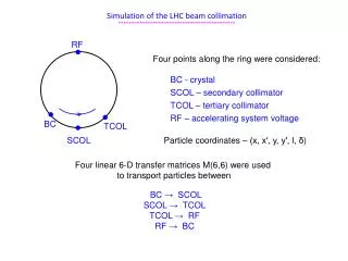
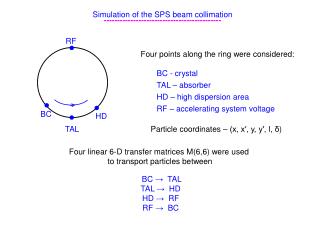
Simulation of the SPS beam collimation -------------------------------------------- RF • Four points along the ring were considered: BC - crystal TAL – absorber HD – high dispersion area RF – accelerating system voltage • • • BC HD TAL Particle coordinates – (x, x′, y, y′, l, δ) Four linear 6-D transfer matrices M(6,6) were used to transport particles between BC → TAL TAL → HD HD → RF RF → BC
SPS azimuths characterization --------------------------------- Start point → BC azimuth Halo generation Halo particles begin hit BC after some turn numbers Due to increase of particle oscillation amplitudes Final points → (1) absorption in TAL (2) Inelastic interactions in BC HD azimuth → off-momentum halo registration RF azimuth → change of particle momentum due to RF voltage V
Beam losses in crystal : experiment ↔ simulation --------------------------------------------- Observation object → loss dependence on crystal orientation Good agreement in the dependence character and angular width Disagreement in loss reduction value R for channeling Experiment → R≈6 Simulation → R≈30 One of possible reasons of this disagreement → crystal miscut
Crystal with miscut ---------------------- Miscut angle θm is between the crystal plane and its surface When crystal plane direction at its entrance is parallel to beam envelope direction Particles enter BC through its side face in first hits First hit When impact parameters of particles b < Δm =0.5 R θm2 their first passages will be as in amorphous matter Δm – prominent part of crystal surface bend Beam losses for this perfect orientation will be increased for crystals with miscut Δm Beam envelope direction
To estimate dependence of beam losses on crystal miscut ----------------------------------------------- Impact parameters of halo particles should be studied With taking into account Betatron oscillations Amplitude oscillation increase Synchrotron oscillations and Model of crystal with miscut should be developed Using the surface potential of crystal near the entrance through its side face
Increase of betatron oscillation amplitude per turn Δxm ------------------------------------------------------- Estimation of halo repopulation time → average increase λ < 1 nm XBC Assumption → exponential distribution P(Δxm)=exp(- Δxm / λ) φ1 • • φ2
Case when RF was switched off --------------------------------------- Distribution of δ is Gaussian with σ = 0.6×10⁻³ , δ=const Particles have orbit shift Xε=Dx·δ Orbit shift determines different values of oscillation amplitudes for particles, which will touch the crystal Amplitude is determined by condition Xbc+Δ=-xm+Dx·δ Δ – distance between closest trajectory part and BC Δ In BC position Dx < 0 For δ > 0 → shift Xε < 0 Amplitude of touch is reduced For δ < 0 → shift Xε > 0 Amplitude of touch is increased Xbc
Impact parameters in Case when RF was switched off --------------------------------------- For average amplitude increase λ= 0.5 nm (1) and 0.1 nm (2) λ is halo propagation rate Particles begin hit BC when they pass the distance Δ after Nt= Δ/λ turns Distribution of impact parameters Distribution width is about 100 λ 50 nm (1) and 10 nm (2) Particle with amplitude value at φ=π close to Xbc=-xm+Dx·δ should be again close to φ=π Number of turns to be again at the same phase point Nq=100 in our case when fractional part of tune – fraction(Qh)=0.13
Impact angles in Case when RF was switched off --------------------------------------- Distribution width is the same for different λ=0.5 nm and 0.1 nm ! Why? FWHH ≈ 5 μrad Density of phase points φi of particles is uniform with Δφq =2π/Nq Particle can hit BC when for its current amplitude value xm at least one phase point is in the interval (φ1 ,φ2 ) at XBC Corresponding condition is φ1 = Δφq /2, φ1 = 2 π - Δφq /2 So, the interval of angles should be with present BC parameters → 4.8 μrad
Case of routine operation with RF switched on --------------------------------------------- Gaussian distributions in longitudinal coordinates (l,δ) were considered Particles change their momentum due to RF voltage Trajectory in longitudinal space Horizontal phase ellipse oscillates → For δ=σ period of longitudinal oscillations is about Ts=150 To and orbit shift Xε=Dx·δ=0.47 mm >> Ns·λ (halo propagation value) Thus, particles touch BC when their momentum is about its maximum, δm
Impact parameters and angles for Case with RF switched on --------------------------------------------------------- To hit BC a particle should have betatron phase near φ=π and longitudinal position near (0,δm ) When particles have already Xm > XBC they will miss the crystal many times Their impact parameters are increased by about Ns times, Xim~ 1μm
Simulation for crystal with miscut ----------------------------------- Conditions for entrance and exit through the side face should be correctly taken into account Potential of the crystal surface was used near the entrance through the side face
Loss reduction change for crystal with miscut ----------------------------------------- Crystal 4 has miscut angle θm=200 μrad Its length 2 mm and bend angle 176 μrad → R=11.36 m Prominent part of the surface bend for crystal 4 → Δm=0.23 μm It is smaller but comparable with average impact parameters Our simulation results show losses of halo particles for perfect orientation of the crystal with miscut are really increased These additional bean losses are larger when halo propagation rate is smaller For amplitude increase λ=0.5 nm per turn → 42% For λ=0.1 nm per turn → 120%
Beam losses in crystal for its amorphous orientation -------------------------------------------------- Multiple Coulomb scattering in crystal is considered in Gaussian approach This gives good description of dechanneling due to scattering by crystal nuclei in short crystals Real angular distribution behind the crystal in amorphous orientation besides Gaussian part has longer tails about 1% due to strong single Coulomb scattering by crystal nuclei Passage number Particles of this tail possessing large angular kicks can more quickly reach TAL aperture This should reduce beam losses value Simulation for our case shows Amorphous level of beam losses may be lower by about 10%
Off-momentum halo registration in TAL2 - determination of collimation leakage -------------------------------------------------- X-coordinate of absorber xTAL → boundary of betatron motion = envelope Xβm(s) = xTAL (β(s)/βTAL)1/2 For run with Pb ions with pz=120 GeV/c → xTAL=-8.361 mm Xβm(sTAL2) = -8.4915 mm ----------------------------------------- Additional X-displacement for off-energy particle with δ≠0 in TAL2 azimuth Xδ(sTAL2) = Dx(sTAL2)·δ Maximum of Xδ is determined by bucket half-height δh=1.539×10⁻³ For TAL2 azimuth s=sTAL2 → Dx=3.4015 Xδ(STAL2,-δh)=-5.2349 mm Maximum of total displacement for bunched particle in TAL2 min Xβ,δ = Xβm(sTAL2) + Xδ(STAL2,δh) = -13.7264 mm
Off-momentum halo for 120 GeV/c protons in TAL2 azimuth ---------------------------------------------------------------------- Ionization losses of protons in bent crystal, ∆δ < 0, lead to their debunching Halo tail appears with X < - max Xβ,δ Xleak ? ↓ Large part of debunched particles have possibility to be collimated at subsequent turns Particles will be lost somewhere in the ring if their coordinate at TAL2 X < Xleak – leakage boundary coordinate Xleak is determined by value of δl for which at HD azimuth SAL with smallest aperture XAL Xβm(sAL) + |Xδ(SAL,δl)| = XAL
Off-momentum halo for 120∙Z GeV/c Pb ions in TAL2 azimuth ---------------------------------------------------------------------- Ionization losses increases up to 6.6 GeV for one passage Three passages through non-aligned crystal are sufficient for debunching Xleak ? ↓ Strong energy losses lead to betatron amplitude increase They more quickly reach TAL aperture To increase channeling efficiency due to contribution of multiple passages It is necessary to increase Xoff distance between BC and TAL
Conclusion -------------------------------------------------- Simulation show (1) Miscut really increases beam losses in channeling orientation This increase may be larger than 100% (2) Calculated level of beam losses for amorphous orientation should be corrected because of contribution from strong single Coulomb scattering It decreases by about 10% (1) and (2) decreasing the calculated loss reduction considerably improve agreement of simulation with experiment Halo propagation rate λ should be measured to use its correct value in simulations