Download
1 / 21
210 likes | 326 Views
UA9 the crystal-assisted collimation experiment at the SPS. W. Scandale for the UA9 Collaboration CERN – IHEP - Imperial College – INFN – JINR – LAL - PNPI – SLAC LAL January 24, 2012. Multi stage collimation as in LHC. The halo particles are removed by a cascade of amorphous targets:

E N D
UA9 the crystal-assisted collimation experiment at the SPS W. Scandale for the UA9 Collaboration CERN – IHEP - Imperial College – INFN – JINR – LAL - PNPI – SLAC LAL January 24, 2012
Multi stage collimation as in LHC • The halo particles are removed by a cascade of amorphous targets: • Primary and secondary collimators intercept the diffusive primary halo. • Particles are repeatedly deflected by Multiple Coulomb Scattering also producing hadronic showers that is the secondary halo • Particles are finally stopped in the absorber • Masks protect the sensitive devices from tertiary halo 0 beam core primary halo 6 6.2 secondary halo & showers 7 secondary halo & showers 10 secondary collimator 1m CFC secondary collimator 1m CFC primary collimator 0.6 m CFC Normalizes aperture [σ] tertiary collimator absorber 1m W tertiary halo & showers >10 Sensitive devices (ARC, IR QUADS..) masks • Collimation efficiency in LHC ≅ 99.98% @ 3.5 TeV • Probably not enough in view of a luminosity upgrade • Basic limitation of the amorphous collimation system • p: single diffractive scattering • ions: fragmentation and EM dissociation
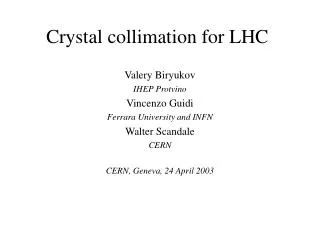
Crystal assisted collimation • Bent crystals work as a “smart deflectors” on primary halo particles • Coherent particle-crystal interactions impart large deflection angle that minimize the escaping particle rate and improve the collimation efficiency θch≅ αbending 3 mm si 1 m CFC amorphous channeling R. W. Assmann, S. Redaelli, W. Scandale, “Optics study for a possible crystal-based collimation system for the LHC”, EPAC 06 <θ>MCS≅3.6μrad @ 7 TeV θoptimal @7TeV≅ 40 μrad 0 beam core primary halo 6 6.2 Multiple Coulomb scattered halo (multi-turn halo) 7 Dechanneled particles in the crystal volume 10 Deflected halo beam Normalizes aperture [σ] secondary halo & showers >10 Silicon bent crystal Sensitive devices (ARC, IR QUADS..) absorber 1m W primary collimator 0.6 m CFC secondary collimator 1m CFC masks secondary collimator 1m CFC Absorber retracted Collimators partially retracted
Potential improvements • Larger impact parameter:crystals deflect the halo particles coherently to a larger angle than the amorphous primary collimator, • better localization of the halo losses • reduced collimation inefficiency ×10-1 expected in LHC from simulations • higher beam intensities (if limited by halo density) • Less nuclear events:inelastic nuclear interactions with bent crystals strongly suppressed in channeling orientation • reduced loss rate in the vicinity of the crystal • reduced probability of producing diffractive events in proton-crystal interactions • reduced probability of fragmentation and e.m. dissociation in lead ion-crystal interactions • Less impedance:reduced amount of material in the beam peripheral • optimal crystals are much shorter than the amorphous primary collimators • primary and secondary collimators are in more retracted positions
Coherent interactions in bent crystals 6. amorphous 5. Volume Capture 4. Volume Reflection P=95÷97% 2. Channeling P=50÷85 % 1. amorphous 3. dechanneling • Two coherent effects could be used for crystal collimation: • Channeling larger deflection with reduced efficiency • Volume Reflection (VR) smaller deflection with larger efficiency • SHORT CRYSTALS in channeling mode are preferred ×5 less inelastic interaction than in VR or in amorphous orientation (single hit of 400 GeV protons) W. Scandale et al, PRL 98, 154801 (2007) W. Scandale et al., Nucl. Inst. and Methods B 268 (2010) 2655-2659.
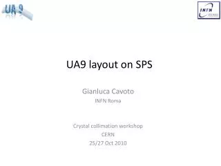
UA9 layout in the SPS Collimation region High dispersion area
UA9 schematic layout ~ 67m / Δμ=90° ~45m / Δμ=60° ~ 45m / Δμ=60° crystal4 crystal3 1m Cu, LHC-type collimator not used in 2011 10 cm Al scraper 60 cm W absorber Medipix in a two sided Roman pot Medipix in a two sided Roman pot Collimation region High dispersion area • Observables in the collimation area: • Intensity, profile and angle of the deflected beam • Local rate of inelastic interactions • Channeling efficiency (with multi-turn effect) • Observables in the high-D area: • Off-momentum halo population escaping from collimation (with multi-turn effect) • Off-momentum beam tails
Crystals • Quasimosaic crystal 1.9 mm long • Bent along (111) planes • Non-equidistant planes d1/d2 = 3 • Strip crystal 2mm long • Bent along (110) planes • Equidistant planes Crystal 3 Crystal 4 • Residual imperfections: • Residual torsion ≈ 1 μrad/mm • Amorphous layer size ≤ 1 μm • Miscut ≈ 100 μrad different paths for different vertical hit points different paths at small impact parameter • Torsion is no longer an issue • torsion over the beam size < critical angle • full mitigation of the detrimental effects Schematic view of the residual miscut angle
Goniometer • The critical angle governs the acceptance for crystal channeling • 120 GeVθc = 20 μrad • 270 GeVθc = 13.3 μrad Transfer function residual inaccuracy |δϑ| ≤ 10 μrad Non-linear part of the transfer function in a full angular scan the drive position changes by 300 µm around the initial value in the plotted range
Channeling efficiency bycoll. scans ~ 67m / Δμ=90° ~45m / Δμ=60° ~ 45m / Δμ=60° absorber collimator Crystal 3 Pb-ion beam at 120 GeV BLMs Proton beam at 120 GeV Efficiency 70-85% Ncoll/Ncry [-] Efficiency 50-74% channeling kick Equivalent crystal kick[μrad]
Loss rate reduction at the crystal ~ 67m / Δμ=90° • Loss rate reduction factor • for protons 5÷8 • for lead ions ≈ 3 • σtot(lead ions)=σh+σed=5.5 b≅10×σtot(p) absorber Nuclear spray Loss rate counters protons Lead ions simulation simulation data ×5÷8 reduction ×3 reduction data
Loss rate reduction at the crystal ~ 67m / Δμ=90° • Discrepancy between data and simulation: • crystal surface imperfections • miscut angle absorber Nuclear spray Loss rate counters protons Lead ions First hit Second hit simulation simulation data ×5÷8 reduction ×3 reduction Miscut angle data
off-momentum halo population ~ 67m / Δμ=90° ~45m / Δμ=60° Off-momentum halo deflected in the dispersive area of the TAL2 Absorber Nuclear spray • P, Pb: diffractive scattering and ionization loss Scraper (TAL2) Medipix in a two sided Roman pot BLMs Off-momentum halo population Linear scan made by the TAL2 (or Medipix) with the crystal in fixed orientation angular scan of the crystal with the TAL2 (or the Roman pot) in fixed position in the shadow of the absorber
off-momentum halo: linear scans proton beams Crystal 4 • Crystal at 4.9 σ • TAL at 7.7 σ scans with the Roman pot of the internal side (momentum loss side) Medipix counts [a.u.] Reduction factor Medipix position [σ] Medipix position [σ]
off-momentum halo: beam tails preliminary Loss rate as a function of the medipix position at the high-dispersion location proton beams Crystal 3 • Crystal at 5.4 σ • TAL at 7.2 σ TAL absorber Crystal • More populated tails on the internal side than on the external side • Particles that have lost momentum are continuously produced by the interactions with the crystal and the absorber edges Beam tails
off-momentum halo: linear scan preliminary Crystal 4 Pb-ion beams 1 σ ≈ 1.2 mm decreasing distance from the beam centre Reduction factor
off-momentum halo: angular scans Crystal 4 close to the crystal proton beams Loss rate as a function of the crystal orientation × 10 • Crystal at 5.6 σ • TAL at 7.6 σ • TAL2 at 9.3σ in the dispersive area • reduction factor in the dispersive area • Decreases due to off-momentum particles produced in the absorber • Increases when the TAL2 is more and more retracted × 5
off-momentum halo: angular scans proton beams preliminary Crystal 4 • Crystal at 5.6 σ • TAL at 7.6 σ • TAL2 at 9.3σ Loss rate along the SPS Sextant 5 amorphous channeling
Perspective for 2012 • The extension of UA9 to LHC is seen favorably by LHCC and by the accelerator directorate (to be announced soon) • time allocation in LHC to be shared in between the machine and the experiments (however very limited) • dedicated run time to avoid conflicts with the high-luminosity operation. • UA9 in the North Area and in the SPS • The main goal will be to validate scenarios, detectors and hardware for LHC • Upgrade of the SPS experimental setup required • crystal collimation scheme for the high-intensity SPS operation. • Preliminary investigations based on UA9 experimental setup • Later an ad-hoc setup is required. • The collimation is requested at high-energy in pulsed mode • Very demanding constraints on crystal acceptance and on goniometer stability UA9 request to the SPSC • 5 days in the SPS (4 with protons and 1 with Pb-ions) • 5 weeks in H8 (3 with protons and 2 with Pb-ions)
New hardware and priorities for 2012 • SPS – 5 full days • High intensity, high flux operation for loss maps along the SPS • Operation with Pb-ions • Hardware test for LHC (crystals and goniometer) • Collimation efficiency of multi-strip crystals • H8 – 5 weeks • Test of new crystals for LHC • Test of instrumentation for LHC • Deflection efficiency with Pb-ions • x-ray spectra PXRas a tool to detect the crystal integrity
Recent publications 1. W. Scandale et al., Physics Letters B 692 (2010) 78–82, “First Results on the SPS Collimation with Bent Crystals” 2. W. Scandale et al., Physics Letters B 693 (2010) 545–550, “Deflection of high-energy negative particles in a bent crystal through axial channeling and multiple volume reflection stimulated by doughnut scattering”. 3.W.Scandale et al. Probability of Inelastic Nuclear Interactions of High-Energy Protons in a Bent Crystal. Nucl. Instr. Meth. B, 268 (2010) 2655. 4.W.Scandale et al. Multiple volume reflections of high-energy protons in a sequence of bent silicon crystals assisted by volume capture. Phys. Letters B, 688 (2010) 284. 5.W.Scandale et al., Observation of Multiple Volume Reflection by Different Planes in One Silicon Crystal for High-Energy Negative Particles. EPL 93 (2011) 56002. 6. W. Scandale et al, JINST, 1748-0221_6_10_T10002, Geneva (2011), “The UA9 experimental layout”. 7. W, Scandale et al., Physics Letters B 701 (2011) 180–185, “Observation of parametric X-rays produced by 400 GeV/c protons in bent crystals”. 8. W. Scandale et al., Physics Letters B 703 (2011) 547–551, “Comparative results on collimation of the SPS beam of protons and Pb ions with bent crystals”. 9. W. Scandale et al., “Status of UA9, the Crystal Collimation Experiment in the SPS”, Invited talk at the IPAC11, San Sebastian, Spain, September 2011. acknowledgments • The EN/STI group was of an extraordinary support to UA9 • BE/OP-BI-RF groups carefully prepared the SPS for our needs • Special thanks to our funding agencies, reference Committees and Referees