Download
1 / 12
120 likes | 262 Views
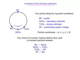
Simulation of the LHC beam collimation --------------------------------------------. RF. •. Four points along the ring were considered: BC - crystal SCOL – secondary collimator TCOL – tertiary collimator RF – accelerating system voltage. •. •. •. BC. TCOL. SCOL.

E N D
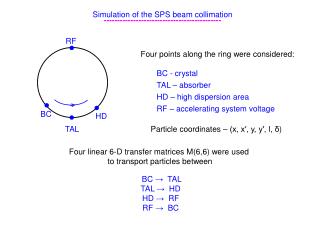
Simulation of the LHCbeam collimation -------------------------------------------- RF • Four points along the ring were considered: BC - crystal SCOL – secondary collimator TCOL – tertiary collimator RF – accelerating system voltage • • • BC TCOL SCOL Particle coordinates – (x, x′, y, y′, l, δ) Four linear 6-D transfer matrices M(6,6) were used to transport particles between BC → SCOL SCOL → TCOL TCOL → RF RF → BC
Simulation of the LHC beam collimation (horizontal) -------------------------------------------- BC positions: TCP.A6L7.B1, s= 19795.1844 xbc=6σx=1.557 mm (7 TeV/c) → 5.949 mm (0.45 TeV/c) SCOL positions: TCSG.6R7.B1, s=20140.5234, xscol=7σx=2.88 mm (7 TeV/c) → 10.01 mm (0.45 TeV/c) TCOL position: TCLA.B6R7.B1, s=20178.4634 RF position: in the middle of the cavities, s=9996.79 with lattice parameters interpolated with voltage summed LHC beam emittanceε=0.5×10⁻⁹ m·rad for 7 TeV/c ε=7.3×10⁻⁹ m·rad for 0.45 TeV/c
LHC azimuths characterization --------------------------------- Start point → BC azimuth Halo generation Halo particles begin hit BC after some turn numbers Due to increase of particle oscillation amplitudes Final points → (1) absorption in SCOL (2) Inelastic interactions in BC TCOL azimuth → halo registration RF azimuth → change of particle momentum due to RF voltage V
Peculiarities of the LHC beam collimation -------------------------------------------- Different distances from the orbit for collimators For crystal collimator Δbc=xbc(0.45 TeV/c) – xbc(7 TeV/c) = 4.392 mm Corresponding change of beam envelope direction ΔXP = (αx/βx)·Δbc= 62.38 µrad -------------------------- Critical channeling angle for (110) Si bent with R=60 m θcb=9.89 μrad (0.45 TeV/c) → 1.96 μrad (7 TeV/c) Multiple Coulomb scattering in 3 mm Si θms=5.91 μrad (0.45 TeV/c) → 0.38 μrad (7 TeV/c) Ratio of coherent to incoherent scattering θcb/θms= 1.67 (0.45 TeV/c) → 5.17 (7 TeV/c) -------------------------- Inelastic nuclear cross-section σin = 507 mb (0.45 TeV/c) → 567.5 mb (7 TeV/c)
Impact parameters and angles for the first hits ------------------------------------- With betatron amplitude increase per turn as in the SPS 0.45 TeV/c 7TeV/c QH=64.31 ΔXP ≈ 1 μrad QH=64.28 ΔXP ≈ 10 μrad Different phase point density
Impact parameters with SCOL for perfect alignment ------------------------------------- 0.45 TeV/c 7TeV/c
Impact parameters with BC for amorphous orientation ------------------------------------- Before extraction (blue) and inelastic interactions in crystal (red) 0.45 TeV/c 7TeV/c The whole crystal works Only crystal surface works
Impact parameters with BC for VR orientation ------------------------------------- 0.45 TeV/c 7TeV/c In both cases the whole crystal works
Channeling efficiency and beam losses ------------------------------------- 0.45 TeV/c 7TeV/c Efficiency is larger than 80% in the range of 25 µrad and 5 µrad, respectively Losses in AM 18% and 75%, respectively
Crystal imperfections: miscut and torsion ------------------------------------- Miscut angle: 60 µrad Loss increase for θo=0, ΔL= 180% Channeling reduction for θo=0, ΔPch=0.7% 1 µrad/mm → ΔL=24% , ΔPch=0.27% Crystal torsion: 2 µrad/mm →ΔL=39% , ΔPch=0.6%
Optimal crystal parameters - ? ------------------------------- L=3 mm, α=40 µrad, R=75 m→ ΔL=-9.4% , ΔPch=0.8% L=3 mm, α=50 µrad, R=60 m → L=4 mm, α=50 µrad, R=80 m → ΔL=0 , ΔPch=0.28% Impact parameters with SCOL for α=40 µrad
Conclusions ---------- 1. Very large beam losses 75% occur in AM crystal (mainly in its surface) Avoid AM-orientations for 7 TeV/c Keep crystal in CH or VR modes 2. Range of 80% channeling: 25 µrad (0.45 TeV/c) and 5-6 µrad (7 TeV/c) 90% channeling: 20 µrad and 3 µrad 3. Effects of crystal imperfections will be sufficiently small when miscut angle ≤ 50 µrad and torsion ≤ 1 µrad/mm 4. Optimal crystal parameters : L=3-4 mm at α=50 µrad 5. Main problem is goniometer fast and accurate and reproducible crystal orientations